I recently resurrected my vacuum tube sonic hologram generator project after recently firing it up after several years and noting to my surprise that everything I had built in it still worked.
It uses inverted crossfed audio delayed much the same way as the Carver circuit does, but what I recently discovered is that when I had designed the delay to be 200uS, it was actually more delay than Carver used for his crossfed channels, which apparently varied from 60 - 140 uS depending on the particular design. I may actually reduce the crossfeed delay slightly, having learned this. The delay was accomplished, btw, with four cascaded 2nd order all pass filters. In the photograph, you can see the JW Miller air core chokes that I stacked to save space. If anybody has a C9 schematic, I'd be interested in getting hold of an electronic copy.
In the photo, you won't see any vacuum tubes, even though there are 12 of them in the 1U chassis. That's because I mounted them inside solid 1.5" pieces of aluminum (at left and right) which I had drilled out and tapped for tube sockets mounted on rubber grommets. The tubes can be accessed by removing the 'heatsink' covers. The two tube positions toward the front of the chassis on each side are HV vacuum tube regulator using a tube reference - one for each channel. I'm using solid state regulation for all tube filaments. One thing I must say for this type of construction, besides being a lot of trouble, is that it really cuts way down on microphonics.
I did some thinking about frequency shaping for the sonic hologram effect and realized that I probably had not been frequency shaping the right way when I had originally built it so I recently made some changes here that seem to have some promise. One problem is that I haven't been able to find good head masking response measurements - just a mathcad simulation that may be overly simplified, but does seem to have some validity. When I adapted the frequency shaping in accordance with these curves, the sense of depth layering is considerably accentuated and the mono or center image is more stable, both good things, at least so far.
I also had reserved a tube on each side to be sort of a phonograph tick and popdelay and analog switch for a future enhancement using a solid state tick and pop filter detector which I never built. Since I still enjoy LPs, I may yet try to get something together here since my LPs aren't getting any quieter")
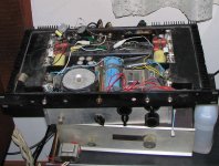
It uses inverted crossfed audio delayed much the same way as the Carver circuit does, but what I recently discovered is that when I had designed the delay to be 200uS, it was actually more delay than Carver used for his crossfed channels, which apparently varied from 60 - 140 uS depending on the particular design. I may actually reduce the crossfeed delay slightly, having learned this. The delay was accomplished, btw, with four cascaded 2nd order all pass filters. In the photograph, you can see the JW Miller air core chokes that I stacked to save space. If anybody has a C9 schematic, I'd be interested in getting hold of an electronic copy.
In the photo, you won't see any vacuum tubes, even though there are 12 of them in the 1U chassis. That's because I mounted them inside solid 1.5" pieces of aluminum (at left and right) which I had drilled out and tapped for tube sockets mounted on rubber grommets. The tubes can be accessed by removing the 'heatsink' covers. The two tube positions toward the front of the chassis on each side are HV vacuum tube regulator using a tube reference - one for each channel. I'm using solid state regulation for all tube filaments. One thing I must say for this type of construction, besides being a lot of trouble, is that it really cuts way down on microphonics.
I did some thinking about frequency shaping for the sonic hologram effect and realized that I probably had not been frequency shaping the right way when I had originally built it so I recently made some changes here that seem to have some promise. One problem is that I haven't been able to find good head masking response measurements - just a mathcad simulation that may be overly simplified, but does seem to have some validity. When I adapted the frequency shaping in accordance with these curves, the sense of depth layering is considerably accentuated and the mono or center image is more stable, both good things, at least so far.
I also had reserved a tube on each side to be sort of a phonograph tick and popdelay and analog switch for a future enhancement using a solid state tick and pop filter detector which I never built. Since I still enjoy LPs, I may yet try to get something together here since my LPs aren't getting any quieter
Attachments
Update: I pulled some data online including schematic for the Burwen TNE7000 (which data wasn't readily available when I built the tube sonic hologram generator) and I think there's a decent chance that I can adapt the control circuit to my design but using a dual triode as an analog switch instead of jfets. I have a little trick circuit to cancel charge injection also.
In case this might seem a bit confusing - the idea here is to do a tube sonic hologram generator AND a tick and pop remover in the same chassis. Either one can be disabled if desired by setting front panel controls appropriately.
Dont' think Richard Burwen would mind - not like I'm gonna cut into his sales at this point in time
- Status
- This old topic is closed. If you want to reopen this topic, contact a moderator using the "Report Post" button.