Idea for a 2Tube 6080 PP amp.
I am about to recieve some 6080's and some 6AS7's and I was just starting to think what I might do with them. I had a crazy idea to build a 2 tube PP amp. The idea would be to have a beefy single pentode driver stage (choke/CCS loaded) and then to do the phase splitting by taking the signal for one of the 6080 triodes from the cathode of the other. In this way it would be possable to build a complete stereo PP amp with just 2 driver tubes and two 6080's. If there wasn't a suitable driver pentode, how about using a ECL86 as the driver and maintaining the two tube approach.
What do you think of my chances of success. I understand that the 6080 and the 6AS7 can be very variable, even within the same envelope. I also understand that cathode bias is mandatory and that these tubes can bias up at wildly different voltages - sounds like a bit of a long shot to get this working, but what do you guys think of my minimalist idea?
Shoog
Yes, that would be my experience with the 6080/6AS7 as well. Might try an interstage transformer and cathode bias the output tubes independently of each other. Some means of trimming the operating point of one against the other is advisable. A single 6080 in pp should be capable of at least 7wrms..
Fixed bias is much more efficient than cathode bias in terms of required HT (HV) but is risky due to warm up issues and the variability of the tube's transconductance making it very sensitive to minute variations in grid bias voltage. A mix of both might be a good compromise.
I believe James, Sowter, and several others make suitable driver/splitter transformers.
Aim for a pk-pk swing of at least 300V to assure that you can drive them to full power.
Several of my friends have built pp amplifiers with these tubes using talema, ulveco or similar toroidal power transformers for the output transformer. As I recall a model with two 120V primaries and two 18V secondaries works well to match to an 8 ohm load, and they're cheap.
Connect the primaries in series, with center tap connection, and connect the secondaries in parallel. If you want to match a 4 ohm load I think a 12V secondaries is close enough.
This equates to a primary Z of about 1.42K ohms plate to plate to an 8 ohm load. This trick probably won't work as well with EI types due to the much higher leakage inductance so use a toroid.
Kevin
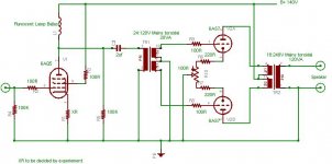
Just an idiot idea not yet checked :
Almost no DC in the OPT so toroîds should be usable.
Yves.
An externally hosted image should be here but it was not working when we last tested it.
Almost no DC in the OPT so toroîds should be usable.
Yves.
I was toying with the idea of using toroidals as outputs, but was a little concerned about DC with such variable tubes. Seperate cathode resistors would seem a must.
I saw listed on a datasheet a completely different operating point for these tubes. 135V anode, 250R cathode resistor, giving a current of 125mA. This means that the grid is at -35V which presumably would lessen the variability of bias. Since my speakers are 4ohm, I would need a 800ohm load which would mean about an 18V:240V which coincidentally is exactly the toroidals I have. The driver design would presumably be much more straighforward at these voltages, how about an improved futterman style driver with the cathode returned to the output.
Good to get some feedback.
Shoog
Hey Shoog,
I'm not so far from that you suggest.
It's designed so that each half 6AS7 draw 100mA and has 115V Vak, bias being 40V.
This already set the plate dissipation at near 12W.
This sleeps in cartons for some month, I plan to build a preamp based on the same topology but with smaller 6n6p triodes before, but I can't tell when
Yves.
It looks interesting and sort of the same, but isn't it running as something like a SEPP. Are the phase splitter and first stage two halves of ECC83, as this maintains the 2 tube philosophy.
I like the idea of running mine at just 135V because I have a big toroidal power transformer which would probably do power supply duty. Mine would be running at just over 0.5A in total.
When the output tubes grid is at -35V, whats the drive voltage which the phase splitter need to supply (70V PP maybe) ? This would mean that the phase splitter would need at least double that across it, so at least 140V.
How would I go about biasing this into more class AB territory. I have never done PP before so don't know about things like this.
Shoog
How about using a mini power pentode to do current amplification, putting it through a toroidal interstage transformer with a 1:10 Voltage ratio. This would do the voltage amplification and phase splitting and would drive 6as7 directly. Simple and elegant.The only issue that would arise would be stability issues if global feedback was needed.
Shoog
Shoog
I wouldn't use a 1:10 step up unless the rp of the driving tube was extremely low as this equates to a 25 fold increase in source impedance to each of the driven grids.. (say 3K rp to 75K effectively at each grid) Mr. Miller would come to town and you would be lucky to have any response above 10kHz.
The designs I have seen all use the toroid as a conventional pp output transformer. Bear in mind the low voltage configuration is going to give you somewhat fewer watts as well. Some means of adjusting dc balance may be advisable.
The designs I have seen all use the toroid as a conventional pp output transformer. Bear in mind the low voltage configuration is going to give you somewhat fewer watts as well. Some means of adjusting dc balance may be advisable.
Good point on the impedence step up. I was thinking that by running a driver tube at 40mA, after stepping up I would still be left with about 7mA to drive the grids of the 6AS7. This would allow me to use the same +B and a low gain driver tube. I would have to go down a different rough and use a a higher voltage input to the transformer and step down the voltage to the grids instead of stepping it up. This would require a voltage doubler at least to get the required voltage to the driver.
I have used toroidals as outputs and they work well. I don't see why they wouldn't work as interstages. The difference between them and a proper (expensive) interstage transformer is that they wouldn't accept DC and so need a RC stage. Other than that there hi bandwidth should make them ideal. I can't imagine that they would produce a worse result than any of the more conventional tube based phase splitters, and there slight imbalances. The only way to find out is to try them.
The output tubes have a 100R pot to balance them.
Shoog
Had another idea. What about making the driver a cathode follower. Give responsability for voltage gain entirely to the interstage transformer. This reduces the output impedance to acceptable levels. I could use another 6080 to do the driver duty, which would be nice because then we are down to a 3 valve amp. Linearity would be less of an issue when run as a cathode follower. However 2.5A heater current is a hard one to swallow for just a driver.
How about a triode strapped EL86, which has a low Ra and is happy to run at relatively low voltages.
Shoog
How about a triode strapped EL86, which has a low Ra and is happy to run at relatively low voltages.
Shoog
HI,
You should apply drive to the upper tube between its grid and its cathode, not relative to the ground.
So, using an interstage tranny, one winding should be referenced to ground, (for thr lower triode) and the other to the cathode of the upper one.
In the idea I showed, this is done by returning the plate load of the phase spiltter to the output and having the primary of the OPT returning to B+.
So the concertina plate is "bootstraped" and enjoy from an apparent supply voltage almost twice the B+.
This IS the trick
Yves.
Shoog said:G
The output tubes have a 100R pot to balance them.
Shoog
I'm sure a 1R pot between the tubes should have enough angular resolutioin to provide easy balance adjustment.
I've been thinking about this to much today (my head hurts). Using the full 10x voltage gain of the interstage would require 100mA of drive current to produce 1mA at the grid of the 6as7, which is not good really. So if I go for 5x voltage gain from the interstage we get a more reasonable current requirement from the driver (I think 20mA for the same 1mA at the grid). However this now isn't enough voltage gain for my needs, so the idea of a cathode follower needs an additional stage with a gain of about 5x. Doing this we could still have everything hunky dory with the "dream of a two tube PP, by using something like a ECL82 or ECL86 to drive it. The ECL82 I have, and can be made reasonably linear by applying plate to plate feedback between the two stages.
Am I on the right track here? How much current do I really need on the grid to keep the top end.
Shoog
Am I on the right track here? How much current do I really need on the grid to keep the top end.
Shoog
ECL82 is the way to go. Taking the output from the anode, but applying local plate to plate feedback, we have an output impedance approaching that of a cathode follower, but with the advantage of the gain we need. Infact we could probably reverse the phase splitting to reduce the the voltage rather than increase it, and still have enough voltage gain.We also have lower distortion to boot. The only thing there would be is that it would definately need a higher +B for the driver to achieve this.
2 tubes, perfect phase splitting, only one cap in the signal path. Sounds as if it might even be good.
Shoog
2 tubes, perfect phase splitting, only one cap in the signal path. Sounds as if it might even be good.
Shoog
Personally, I wouldn't use any step-up at all in the IT. The chances of it working well are slim.
I think a single 6SL7 would be able to produce the necessary voltage swing when driving a 1+1:1+1 interstage with your supply voltage of 135V with plenty of voltage gain. It would probably not be able to do it if loaded by plate resistors, but the IT puts (nearly) the full supply voltage on the plates.
Connect the cathodes of the 6SL7 together and put a simple CCS under them. You would need a negative supply of -10V or so, but it only needs to deliver a few milliamps.
The grids of the 6080 are not hard to drive because the Miller capacitance is low.
I have the solution.
A 5687 driver with CCS or Choke load. Works quite happily at 120V Anode and 15mA.
Put this through a 55V:110+110V to do phase splitting and 2X voltage gain. This leaves me with 7mA drive for the grids of the 6080, which should be more than adequate.
So three tubes, two CCS and two interstages. One coupling cap. I will probably have a seperate valve rectifier for the 5687 to get the best out of the critical driver stage.
Shoog
- Status
- This old topic is closed. If you want to reopen this topic, contact a moderator using the "Report Post" button.
- Home
- Amplifiers
- Tubes / Valves
- Idea for a 2 tube 6080 PP amp.