I have been working on this preamp for about 2 years now. The latest alterations have produced a significant leap in performance so I thought I would share it.
The whole project started with the Vacuum State Valve Buffered Inverted Gainclone. I built the vary basic version as described in Joe Rasmussens article. I decided to try to emulate his more sophisticated version with a Valve CCS and a MOSFET constant voltage. As explained in Joes original article, by keeping the output valve at a constant current and at a constant voltage we get all the benefits of a Cathode follower but without its main disadvantage,ie 100% cathode feedback - which is widely recongnised as robbing the sound of life and punch. I built a few versions of this at various voltages and was happy with the result - enough so that when I decomissioned the Gainclone I kept the buffer on as my main preamp.
However it had one main disadvantage and one minor one. The main one was that as a cathode follower it was unity gain which wasn't quite enough for my power amp. The minor disadvantage is that it was a fraction bass shy.
I then went back to the vacuum state website and looked at the FVP5. This inspired me to convert my split rail buffer into a single supply preamp and to add a voltage gainstage. This was a big improvement, with extra gain and increased bass punch.
I then got involved in a thread about LED bias for valves and introduced it for the output stage. This was a help. I then tried a Green LED on the cathode of the voltage Gainstage. This produced a soft and smudged sound which was due to the low current through the LED of only 4mA. Further discussion suggested apply supplementary current to bias up the LED into a more linear range. This I did with a little circuit off the heater supply. This was a signicant improvement over the unboosted LED or an unbypassed resistor.
This final design is very detailed with a very natural top end and a powerfull bass. Its only disadvantage is the it has a little bit to much gain. The voltage gain valve could usefully be replaced with a lower MU tube for a lower gain overall. The only thing to consider is that the voltage on the grid of the second stage needs to be half the +B voltage plus a few volts.
It only remains to thank Joe Rasmussen for the original inspiration and the fundamentals of the circuit design. I also would like to thank SY for his ideas and help on LED bias.
Shoog
Attachments
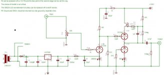
I have made a slight modification since posting the original circuit. I have changed the 1K resistor, which supplies the anode of the first stage, to a 660R. This is because the 1K produced a slightly bloated bass sound. As I said in the circuit, I suggest using a 1K5 pot to tune this to your exact taste. You can achieve a very full on hard sound or a very smooth sound by slight variation of this value.
Shoog
Shoog
PSU
Hi,
In my opinion is the superregged PSU form the original design from Allen a balanced PSU, as on the other hand this schema uses a unbalanced PSU with a different value of 156V DC
Is it therefore dificult to compare thes PSU's ??
Greetings
Maikel
PS: spare me, I'm a newbie")
Hi,
In my opinion is the superregged PSU form the original design from Allen a balanced PSU, as on the other hand this schema uses a unbalanced PSU with a different value of 156V DC
Is it therefore dificult to compare thes PSU's ??
Greetings
Maikel
PS: spare me, I'm a newbie
The power supply I used was a simple 5 stage CRCRCRC filter. IT is said in the original design that the superreg is central to the sound of the circuit.I cannot comment as I have never heard the superreg.
However in my small experience the simple RC filters often sound superior to regulated supplies.
The 156V supply can be varied but you will have to adjust the circuit to compensate. This shouldn't be to difficult.
Shoog
However in my small experience the simple RC filters often sound superior to regulated supplies.
The 156V supply can be varied but you will have to adjust the circuit to compensate. This shouldn't be to difficult.
Shoog
Hi Shoog,
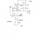
I made some calculations of the working point of the tubes, assuming 2V drop for the red led the SLCF works at roughly 5mA and slightly less than 80V, right?
Inspired by this thread I cooked up my version of the tube buffer you proposed time ago, using asymmetrical split supply (+100 and -50V), a C4S current source (instead of the lower tube) and a IRFD110 Mosfet for the constant voltage bootstrap.
Tested it on my scrap speakers and, tough I can't comment about the sound, it seems to work quite well.
The simple cathode follower was surely worse.
Thanks Shoog for sharing (and of course Joe Rasmussen!)
Cheers
Andrea
Attachments
Hi Andrea,
Good to see you gave it a go, looks good to me. The exact bias point needs to be carefully set to get the best out of this circuit- experimenting is the only way really.
If you try it on your main system please report your impressions so that others can decide whether to try it.
Just got back from a weeks holiday and my main amp is down bummer .
.
Shoog
Good to see you gave it a go, looks good to me. The exact bias point needs to be carefully set to get the best out of this circuit- experimenting is the only way really.
If you try it on your main system please report your impressions so that others can decide whether to try it.
Just got back from a weeks holiday and my main amp is down bummer
.Shoog
Shoog said:The power supply I used was a simple 5 stage CRCRCRC filter. IT is said in the original design that the superreg is central to the sound of the circuit.I cannot comment as I have never heard the superreg.
However in my small experience the simple RC filters often sound superior to regulated supplies.
The 156V supply can be varied but you will have to adjust the circuit to compensate. This shouldn't be to difficult.
Shoog
Hi Shoog,
Did you manage to resusitate you're amp??
Can you post the 5 stage CRCRCRC filter schema?
Did you manage to compare the sound of the FVP5 to you're design??
I never build a tube-amp, and I heard that building a phono-amp is even more difficult because of sensitivity. But I want to build a real high-end phpno-amp (MC)
That's why I think it's more realistic to build you're amp than the FVP5.
What do you think, and do you have any tips / suggentions for me?
Thanx very much for you're comments and time
Maikel
well I haven't heard a Vacuumstate product without a superreg (Allen uses them in everything tube that he makes) but I can say with them his designs are among the best sounding I have heard personally. I have had a FVP at my place for about 1 1/2 months in the past and currently have an RTP-3D at my place for review. Both are seriously good preamps (the RTP-3D is probably one of the best). BTW, the FVP has now been replaced by his new SVP (six valve preamp). He is also using this superreg in his DPA300B amplifier (on the input stage).
If I were to build a new DIY design now I would seriously consider using this shunt regulator as it seems easy to implement and apparently from the sound of Allen's gear, it really works well.
If I were to build a new DIY design now I would seriously consider using this shunt regulator as it seems easy to implement and apparently from the sound of Allen's gear, it really works well.
I never heard the FVP5 or a superreg. I would guess however from the reviews of the FVP5 that I have read, that the sound of my implementation is very similar. Mine is clean and clear with plenty of punchy but controlled bass.
I built a CCS loaded 5687 preamp and though I liked it a lot, it was far less neutral than my suggested design.
Mine is relatively simple to build and only used 3 valves plus a rectifier..
On the matter of the Power supply, I would suggest starting from the transformer you can lay your hands on and then using Duncanamps PSU2 simulation program to derive a suitable supply. I have used salvaged computer power supply caps with a final high quality bypass. The total current draw of the amp is about 16ma.
Good luck.
Shoog
Hi Shoog, in testing I found that a green LED bypassed with a cap greater than about 25uF bettered the performance of red and IR LEDs, bypassed or not. Residual distortion was below the limits of a 24-bit DAC. It's a good solution for those who don't mind the cathode cap. Have you considered an IXYS chip for the current source? Though it's also probably a better technical performer the main benefit is simplicity. A couple of resitors and an IC. Might save you some work.
rdf said:Have you considered an IXYS chip for the current source? Though it's also probably a better technical performer the main benefit is simplicity. A couple of resitors and an IC. Might save you some work.
Hi,
I was also thinking about it: if I were to use 2 triodes for the SLCF I would use the second triode for the bootstrap element and use a SS CCS to load the cathode follower.
This is because one of the schematics @vacuumstate suggests that there might be problems with the non-linearity of the Fet capacitance.
On the other hand, as John Broskie suggested while presenting the Aikido, loading a tube with a similar device is a good thing... so probably the all-tube solution is the best soundwise...
Cheers
Andrea
My apologies for the at-work shorthand. I should have specified the circuit used to current bias the green cathode LED. The LED has a dynamic AC impedance of ~12 ohms, the 330 ohms looks close to a current source. A SS CCS however would afford a huge reduction in potential noise injection from the AC line and do a much better job injecting a truly constant current.
I read somewhere that the FVP5 sounds better with the tube constant voltage element, however this requires another valve and a higher voltage. As I said originally this design evolved out of a split rail valve buffer, and introducing another valve at the top means that the rails would have to be unbalanced and precisely tuned. With the design as is everything fell into place with regards to voltages in a split rail valve buffer. When it evolved into its current form, again the voltages fitted nicely so I left things as they were.
I know that the triode based CCS is not a great performer, but is its performance good enough for the job. Are the swings of introducing a silicone CCS going to be outwayed by the sonic roundabouts of introducing silicone. Would we be chasing diminishing returns. Personally I think it performs well enough. With regard to noise issues, I run a very sensitive setup and I have never had any kind of noise issues from my preamp. If the rails are smooth enough then noise shouldn't be an issue. Again it works adequately- so why improve it.
The FET functions as a cathode/source follower which is the least prone to gate capacitance. How would you tell if it was a significant issue, there is no high frequency roll off to speak of. Use a better FET if you think it would help.
This is a carefully tuned design, once you start changing one element you have to retune all the other elements to compensate. If you want the performance of the FVP5, then its not significantly more complex than my design. I like my design because it performs well and has an elegant simplicity. Don't take offence, but I think the choices I made were the right ones. The original FVP5 is probably degrees more tuned, the design is out there so make your choice.
Shoog
Shoog you are right,
it's all a matter of choices
My post wasn't meant as criticism but as a sort of white paper (or loud thinking ) to brew my own version or to let someone else do something similar.
Of course a tube bootstrap would require more B+, especially if one wants to keep the tube CCS.
About your circuit, at which current does the SLCF work ?
I'd say about 10ma, can you confirm this?
Cheers
Andrea
it's all a matter of choices
My post wasn't meant as criticism but as a sort of white paper (or loud thinking
) to brew my own version or to let someone else do something similar.Of course a tube bootstrap would require more B+, especially if one wants to keep the tube CCS.
About your circuit, at which current does the SLCF work ?
I'd say about 10ma, can you confirm this?
Cheers
Andrea
Nearer to 7ma through the SLCF.
If tweaking the design and wanting to include a valve at the top, it shouldn't be to difficult. You will need to think of around another 80-90V on the +B, you will want to keep the current through the voltage gain stage about the same, and also keep the voltage on the plate of the first tube about the same. I think the current through the first valve is about 4ma. As I suggested before using a pot as the last RC filter element of the first stage, will allow you to find the sweet spot by trial and error, and then substitute with a fixed valve resistor.
Shoog
RIAA ?
Hi Shoog,
another stupid question
Does you're schema include RIAA correction ?
I want to use a 'choke-input - voltage regulator - choke output' PSU. I included the schema as an attachment (as you can see it is the toccata psu designed by Loesch).
I think the zener D1N750 (4,7V) is for protection-purpose...
Thanx again,
Maikel
Attachments
- Status
- This old topic is closed. If you want to reopen this topic, contact a moderator using the "Report Post" button.
- Home
- Amplifiers
- Tubes / Valves
- My version of the Vacuum State FVP5