Morgan Jones shows several examples among them a 4 stage RC circuit, where he uses a total of 2k in resistors aka 4 X 500ohms.
What I didn't understand is how he got that number, what seems to be a default or recommended value of the value of resistors in RC filtering. Of course the higher the value, the better ripple rejection but also higher voltage drop and higher output resistance. MJ doesn't discuss this....
Phono stages could probably use more resistance, but how about a output stage?
Knubie
"5 stages of RC says nothing. What R´s, what C´s.
bridge rectifier? How much current?
Buy Morgan Jones "Valve amplifiers", ther are simple formulas
to get the ripple down with RC stages,"
El Cheapo Valve phone.
100uf, 100R, 100uf, 100R, 100uf, 100R 100uf, 100R, 100uf, 100R 100uf 1uf
The 5 stages are adequate for the job. On phono stages tiny things can cause significant hum issues - after a certain point though it becomes more and more difficult to track down the last little bit of hum, and the effort just isn't worth it. I can live with the small amount of residual hum, its only really an issue when listening on headphones.
Another user may think any hum unacceptable.
Shoog
What is the advantage of using a Bridge rectifier (four diodes) v a full-wave rectifier (two diodes)? I ask this because the change in cost from one to the other is nill and if one is far superior i'll use that one.
This project is more or less on the back burner of my DIY stove (The amplifier being front, and center) However, I deeply value all of the advice, and the knowladge that I have learned through this thread.
This project is more or less on the back burner of my DIY stove (The amplifier being front, and center) However, I deeply value all of the advice, and the knowladge that I have learned through this thread.
Just one of several conventions for labeling parts commonly used here and abroad.
The multiplier takes the place of the "." in the component value.
For example:
51K1 is equivalent to 51.1K which is a standard 1% value in the E96 range.
For values below 1K substitute R instead, so 10.0 ohms for example becomes 10R0, while 100 ohms becomes 100R.
2u2 is the same as 2.2uF
MKP is simply a type of film capacitor. You can use any film type you like as long as tolerance, value, and voltage are suitable.
Etc.
Konnichiwa,
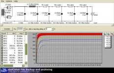
Using a 100R resistor instead of my originally specified 1K moves the "Corner" frequency for each RC cell up a decade. Each 1K & 100u RC cell will have a corner frequency of < 2Hz, so 20Hz will be reduced by 20db and 100Hz by 34db, per cell.
Using 100R/100u moves the corner frequency to around 20Hz and at 100Hz only by around 16db. So in 5 cells you loose around 90db filtering at 100Hz compared to my original circuit.
With 10u input capacitor the ripple is in the region of 10V. Your circuit will attenuate this by a factor of 10,000 to around 1mV, my original one will (theoretically) kill the 10V ripple by a factor of 40,000,000,000,000, in other words any junk from the mains and hum will be theoretically dropped well into the picovolt range (three orders of magnitude lower).
With real capacitors the amount of attenuation is less due to parasitic resistive and inductive behaviour so we probably "only" get noise down into fractional milli to microvolt, which I think is good enough for government work.
So, see if you can find yourself some extra volts on that transformer of yours and up the resistors, increasing the capacitor values will also help, you could go 330R/330u and have the same filtering as 1K/100u for 1/3rd of the voltage loss. Or you could stick a choke into the first stage, many options.
I find 100u/450V and 1K resistors exceedingly cheap and hard to mess up....
Sayonara
Shoog said:El Cheapo Valve phone.
100uf, 100R, 100uf, 100R, 100uf, 100R 100uf, 100R, 100uf, 100R 100uf 1uf
The 5 stages are adequate for the job. On phono stages tiny things can cause significant hum issues - after a certain point though it becomes more and more difficult to track down the last little bit of hum, and the effort just isn't worth it. I can live with the small amount of residual hum, its only really an issue when listening on headphones.
Using a 100R resistor instead of my originally specified 1K moves the "Corner" frequency for each RC cell up a decade. Each 1K & 100u RC cell will have a corner frequency of < 2Hz, so 20Hz will be reduced by 20db and 100Hz by 34db, per cell.
Using 100R/100u moves the corner frequency to around 20Hz and at 100Hz only by around 16db. So in 5 cells you loose around 90db filtering at 100Hz compared to my original circuit.
With 10u input capacitor the ripple is in the region of 10V. Your circuit will attenuate this by a factor of 10,000 to around 1mV, my original one will (theoretically) kill the 10V ripple by a factor of 40,000,000,000,000, in other words any junk from the mains and hum will be theoretically dropped well into the picovolt range (three orders of magnitude lower).
With real capacitors the amount of attenuation is less due to parasitic resistive and inductive behaviour so we probably "only" get noise down into fractional milli to microvolt, which I think is good enough for government work.
So, see if you can find yourself some extra volts on that transformer of yours and up the resistors, increasing the capacitor values will also help, you could go 330R/330u and have the same filtering as 1K/100u for 1/3rd of the voltage loss. Or you could stick a choke into the first stage, many options.
I find 100u/450V and 1K resistors exceedingly cheap and hard to mess up....
Sayonara
I actually used the 1K/100u route posted by Thorsten for my headphone amp and I can tell you I'm pretty surprised at the result. AC feeding the filaments of the tubes, and I get just nearly audible hum (when you're all alone in a very silent room) with this method, volume control at any position.
Makes me think twice about DC heating and my planned MOSFET high voltage regulation for the B+.
I also used the same scheme for mt 12B4 preamp and at 0 volume, it's dead silent (by ear from listening position). I have a problem with my ALPS though as it sort of buzzes a bit at 10 o'clock, 1 o'clock, 3 o'clock positions.
I forgot to mention that I also have a quite large choke as the second stage. The transformer can't supply any more voltage so a new transformer would be the only way to kill that last bit of supply hum. My main point though is that there are other sources of hum and sometimes nothing short of a complete rebuild will nail those.
I'am real anti DC heaters. Its a rare circuit that really needs them. A phono amp is one of those rare instances. There are enough anicdotes out there saying that AC sounds better to pay attention. These things are designed for AC so why some audiobuff thinks it needs DC is beyond me. There are some valves that are prone to heater hum pickup (5687 springs to mind) and there DC heaters are called for.
Shoog
arnoldc said:Makes me think twice about DC heating and my planned MOSFET high voltage regulation for the B+.
Already done
")
http://giaime.altervista.org/mypreamp.html
scroll down the page for a Mosfet regulated B+, a nice phono stage and a nice linestage.
Hi Giaime, I actually visit your site from time to time and I've considered that design of yours. What component values do I have to change for output other than 220V? The other one I'm considering used a string of zeners to set the output voltage which to me is easier (I'm lazy  )
)
)EC8010 said:Giame, some of your horizontal lines don't show up on my computer!
I found that true for the thumbnails, but clicking on the pictures to view full-sized cured all.
arnoldc said:Hi Giaime, I actually visit your site from time to time and I've considered that design of yours. What component values do I have to change for output other than 220V? The other one I'm considering used a string of zeners to set the output voltage which to me is easier (I'm lazy
Hello, thank you very much for the interest
You have to change R7. Watch out for dissipation!!!! Don't put a trimmer there, it will burn. Try with fixed resistors of at least 2W rated dissipation. I'm using 3 1/2W resistors and they get very hot.
And... a note for everybody: not ALL of the circuits posted in my website sound good. All works, but they're not great. As you can see, I'm developing better circuits
Last ones are my definitive, they sound so good especially the linestage.Alexmoose:
Bottlehead offers the Seduction phono preamp. I don't have one, but their Foreplay preamp was a terrific project and sounds too good to be true.
Regards,
Scott
...sounds like the designer has an issue with 'pornography'... I find it somewhat 'off-putting', being reminded of where his mind was residing at the time of his design concepts...
Last edited:
...sounds like the designer has an issue with 'pornography'... I find it somewhat 'off-putting', being reminded of where his mind was residing at the time of his design concepts...
I think the point was to come up with memorable names for all of these products, and what male mind isn't thinking of these things most of the time?
The designs are targeted at the entry level end of the market, I have a number of friends who have built and indeed are still using them - particularly the Seduction which is pretty popular.
...sounds like the designer has an issue with 'pornography'...
Sounds like he also has an issue with drugs. AVOID AVOID. You really have to think it twice before buying gear from him - those types of persons cannot be relied upon (I know from personal experience). Some bodily fluids or some white dust may still be present on his gear. Call the local police if in doubt, you know, if you detect abnormal stains and such.

Crack OTL Headphone Amplifier Kit
- Status
- This old topic is closed. If you want to reopen this topic, contact a moderator using the "Report Post" button.
- Home
- Amplifiers
- Tubes / Valves
- Diy Tube Phono Preamp