Hi,
The heaters of my 12ax7 / 12aT7 tubes are being pushed way above their rated heater cathode voltage.
I know i need to float them, i think 75V is a good value to float at. I am using the Aikido circuit with an HT of 300V fed from tube regulators.
My heaters are currently run at DC from a silicon rectifier.
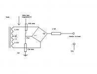
Is this the correct way of wiring the DC heaters for a 75V float without smoke?
(I have a 3.15 - 0 - 3.15 heater tap) which i think i need to leave unconnected?
Cheers
Craig
The heaters of my 12ax7 / 12aT7 tubes are being pushed way above their rated heater cathode voltage.
I know i need to float them, i think 75V is a good value to float at. I am using the Aikido circuit with an HT of 300V fed from tube regulators.
My heaters are currently run at DC from a silicon rectifier.
Is this the correct way of wiring the DC heaters for a 75V float without smoke?
(I have a 3.15 - 0 - 3.15 heater tap) which i think i need to leave unconnected?
Cheers
Craig
Attachments
Can't make out what your diagram is trying to convey.
You can achieve your desired result by using a voltage divider from the HT and tying this to your heater return rail. Some advocate bypassing the bottom resistor of your voltage divider by I generally haven't found it helps.
Alternitively you can tie your voltage divider to the centre tap of your heater winding. This will lift the whole supply to 75V
Hi Shooq,
Sorry my diagram isnt excellent its a paint attempt")
I think i know what your saying and it makes sense to me.... so i connect the CT of my two 3.15V windings to the centre of my potential divider from my HT, then connect the -ve of my rectifier to the CT and the return of the heaters to the CT?
The only ground connection is from the bottom of my potential divider.
I just want to be absolutly clear as if i fry this transformer there is no chance of a replacement!
Thanks
Craig
Sorry my diagram isnt excellent its a paint attempt
I think i know what your saying and it makes sense to me.... so i connect the CT of my two 3.15V windings to the centre of my potential divider from my HT, then connect the -ve of my rectifier to the CT and the return of the heaters to the CT?
The only ground connection is from the bottom of my potential divider.
I just want to be absolutly clear as if i fry this transformer there is no chance of a replacement!
Thanks
Craig
Craig,
I think you've got it right. The drawing is slightly confusing because there is a missing connection between the heater conection in the lower right corner and the negative side of the bridge, but I'm sure you intended that connection. Just leave any CT unconnected as you show it. You might consider a small cap from the HT divider/negative bridge terminal to ground to kill any noise coupled via the heater transformer's primary-to-secondary capacitance.
I think you've got it right. The drawing is slightly confusing because there is a missing connection between the heater conection in the lower right corner and the negative side of the bridge, but I'm sure you intended that connection. Just leave any CT unconnected as you show it. You might consider a small cap from the HT divider/negative bridge terminal to ground to kill any noise coupled via the heater transformer's primary-to-secondary capacitance.
Thanks Brian!
i'm clear on what to do now, ill whack a few microfarads in on the divider. Not too much though because i dont want to risk sending my regulators into oscillation.
I guess if i did connect the CT of the heaters to the floating ground i would only get half the heater voltage instead of the 6.3 i require.
Cheers
Craig
Connecting the CT of your heaters to the 'floating ground' would not short out half your heater supply. The floating ground is relatively 'high impedance'.
It is important to ensure your heater circuitry, from the xfmr to the heaters, is not connected to the main circuitry or B+, except just at the floating ground.
It is important to ensure your heater circuitry, from the xfmr to the heaters, is not connected to the main circuitry or B+, except just at the floating ground.
- Status
- This old topic is closed. If you want to reopen this topic, contact a moderator using the "Report Post" button.
- Home
- Amplifiers
- Tubes / Valves
- Aikido tube heater floating