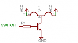
Has anyone used the following, or similar, circuit to switch a tube heater? I'm looking for a transistor to use, but I think I might need to use a darlington pair.
Current is 600ma, hfe min 120-200. A MJE340 would almost do it with a small driver transistor with high hfe (BC547?).
Current is 600ma, hfe min 120-200. A MJE340 would almost do it with a small driver transistor with high hfe (BC547?).
Attachments
A FET was the answer. I tried to reply earlier, but my post was being still being moderated.
I remembered I had a few IRLZ44 power FETs in my junk box. This tested great, so I etched the board and used the FET.
The purpose is to give a PIC control of the heater. This amp (gainclone with tube preamp) is remote controlled. The PIC has a startup sequence, activated by the remote, that does the following:
1. Turn on heater.
2. 20 second delay
3. Start B+ SMPS (240 volts)
4. Start gainclone SMPS (+35 volts)
5. Increase volume to previous setting (before last shut down sequence)
There is no interface on the PCB - everything is controlled from a remote. I really like this design. I'm still waiting on the digital pot IC, but everything else works great.
I'm very happy with the SMPS for the tube supply. I substituted a soft recovery diode for my standard MUR160, and used some big caps with a choke in a C-L-C configuration. No switching noise, even at maximum volume.
- Status
- This old topic is closed. If you want to reopen this topic, contact a moderator using the "Report Post" button.