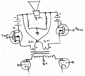
I was just playing around with the Circlotron circuit a bit and came up with an output stage that should be very transparent. By transparent, I mean it puts out the same exact current it is driven with, but provides voltage gain and hence power gain.
First up is a 2X booster, this can be tacked onto an existing amplifier to get twice the power (nice 2X power booster for SE). It should be a nice Hybrid Amp output stage also.
Usually I see a silicon complementary follower stage tacked onto a tube voltage driver amp for Hybrid designs. This 2X booster should preserve the tube sound better.
Don
Attachments
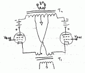
Next up is a higher gain version, this could be used to boost the power of a SE amp transparently for example. Using a typical 40% UL P-P xfmr will give 3.5X power gain. (and no air gap required in the output xfmr)
The output primary current is exactly the same as supplied by the driver input stage. The voltage across T1 secondary appears between the output CT and the cathode or "UL" taps. The grounded grid tubes supply the remaining voltage and power to the output primary. Moving the cathode taps closer to the CT gives higher voltage gain and similarly higher power gain.
Don
Attachments
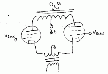
OK, I know some are wondering why not just use grounded grid P-P and skip the Circlotron complexity (see attached). The ggPP version has high output impedance and poor damping. This is because the driver only sees 1/gm (of the output tubes) as a load, the actual load is not reflected back to the driver. So no triode plate feedback to keep output z under control.
The Circlotron version reflects a sample of the output voltage back to the driver stage (voltages from the output xfmr CT to cathode taps).
(and particularly accurately if the output tubes have large gm, so as to not dilute the output signal sample with their grid drive requirements, high gm Mosfets will paradoxically preserve the driver tube sound the best here. Using triodes for the outputs will also work well, since they effectively feedback load effects back to drive requirement effects)
Don
Attachments
- Status
- This old topic is closed. If you want to reopen this topic, contact a moderator using the "Report Post" button.


