LEDs have a bad reputation for bias use. I hear a lot of people say diodes are non linear etc etc but its mostly rumor. I wired up a single triode gain stage with an old red LED for around 15ma bias and measured excellent results. No visible distortion to 200khz, the limit of the signal generator. Its cheap to implement and worth a listen.
That's precisely the point of my experiment. I've read mixed good/bad reactions on LED use for bias with no supporting explanation. That's why DIY Audio is also different, we have people like SY 
I'm enjoying my mod right now and I will modify all my projects that use 417A with cathode resistor bias.
I'm enjoying my mod right now and I will modify all my projects that use 417A with cathode resistor bias.
Well, maybe. I did a round of bench testing last night on a variety of LEDs - red, green and yellow. Each was biased at 10 ma with an IXYS solid state constant current source and a 800 Hz, 1 Vp-p signal was fed into a 1000 ohm resistor connected at the LED-CCS junction. This is roughly equivalent to 1 ma p-p injected into the LED. An FFT of the junction voltage revealed all LEDs show a second harmonic roughly 50 dB below the residual fundamental (already ~55 dB down itself in this circuit.) An eight ohm resistor - that value being equivalent to the AC impedance of the best LED - showed no 2nd harmonic above the noise floor of the test jig. The best LED was an unmarked, small red LED, the worst an identical looking Mode model! Raising the bias current from 10 ma to 15 ma took another 6-8 dB off the second harmonic and (wasn't paying a lot of attention to this part) 1-3 dB off the fundamental for all those tested.
Obvious in hindsight I guess. Since the LED has an AC impedance greater than zero some AC signal will always appear across it, and AC signals across diodes get rectified. Also an LED's impedance is a function of bias current and type, nothing others haven't already noted. What it does suggest though is that LEDs work best in specific applications. The 6C45 driver of my EL84 amp for example is relatively high DC bias (12 ma), loaded by a constant current source and drives a 920 kohm grid resistor. These conditions minimize the AC current through the diode and might be the reason it works so well for me.
In other words these results suggest to me that dropping a LED in place of a cathode resisistor without regard to colour, DC bias and AC current could well result in 'funnies'. Personally I wouldn't consider, say, a blue LED for a mildly biased interstage-loaded tube without a whole lot of testing. From a bit of Googling it appears in terms of impedance that infrared LEDs show the highest promise if the low voltage drop suits your circuit's needs. They're available in high power versions good for 100 ma and the impedance curves appear the most linear and steep in the 10-20 ma range. No 24 hour LED stores open Sundays around here so that's an experiment for another day.
I did a round of bench testing last night on a variety of LEDs - red, green and yellow. Each was biased at 10 ma with an IXYS solid state constant current source and a 800 Hz, 1 Vp-p signal was fed into a 1000 ohm resistor connected at the LED-CCS junction. This is roughly equivalent to 1 ma p-p injected into the LED. An FFT of the junction voltage revealed all LEDs show a second harmonic roughly 50 dB below the residual fundamental (already ~55 dB down itself in this circuit.) An eight ohm resistor - that value being equivalent to the AC impedance of the best LED - showed no 2nd harmonic above the noise floor of the test jig. The best LED was an unmarked, small red LED, the worst an identical looking Mode model! Raising the bias current from 10 ma to 15 ma took another 6-8 dB off the second harmonic and (wasn't paying a lot of attention to this part) 1-3 dB off the fundamental for all those tested. Obvious in hindsight I guess. Since the LED has an AC impedance greater than zero some AC signal will always appear across it, and AC signals across diodes get rectified. Also an LED's impedance is a function of bias current and type, nothing others haven't already noted. What it does suggest though is that LEDs work best in specific applications. The 6C45 driver of my EL84 amp for example is relatively high DC bias (12 ma), loaded by a constant current source and drives a 920 kohm grid resistor. These conditions minimize the AC current through the diode and might be the reason it works so well for me.
In other words these results suggest to me that dropping a LED in place of a cathode resisistor without regard to colour, DC bias and AC current could well result in 'funnies'. Personally I wouldn't consider, say, a blue LED for a mildly biased interstage-loaded tube without a whole lot of testing. From a bit of Googling it appears in terms of impedance that infrared LEDs show the highest promise if the low voltage drop suits your circuit's needs. They're available in high power versions good for 100 ma and the impedance curves appear the most linear and steep in the 10-20 ma range. No 24 hour LED stores open Sundays around here so that's an experiment for another day.
That -50 dB number is better than I can measure, so it may well be true. I assume you saw no higher order harmonics?
Your observation about not knowing what it will be until tested is certainly true. And your observation that the biasing current MUST be thought through is screamingly true. I would never use a LED at 2mA.
The nice thing about maximizing plate load is that you minimize the current swing. One would expect that the 2HD content would scale roughly with current swing, so using high values of plate load (CCS if possible) is good engineering practice.
Thank you SY for reminding us that current swing is important. It would seem to me that using an LED to bias an input tube running a couple of mA, then swamping that with a couple 10's of mA to bring the resistance into a linear range could work really well. On the other hand, a driver biased at 20mA swinging 10mA might introduce quite a bit of 2nd HD.
More tests are required, but it's just too sunny at the moment. Third harmonics did appear with enough generator signal. The circuit is being fed from the headphone output of an M-Audio Aduiphile USB. A volt P-P into 1000 ohms is about its maximum happy output, at higher levels the distortion components of the USB headphone amp begin to peek above the noise at the jig's input. I suspect a complete monotonic sequence of harmonics is buried in the mud.
One aspect of what I found doesn't make sense, at least to me, and also requires testing with different LEDs and frequencies before making too much of it. Bypass caps seem to affect the harmonics to a greater degree than simple voltage divider rules would imply. Values below 10 uF had almost no visual effect - using a ~8 ohm red LED - on fundamental or harmonic. Between 20 uF and 30 uF the fundamental drops a couple of dB, the second harmonic more than 15 dB. Perhaps an issue with the test rig, I don't know and am not sure how to appoach it. When the sun goes does that is...
One aspect of what I found doesn't make sense, at least to me, and also requires testing with different LEDs and frequencies before making too much of it. Bypass caps seem to affect the harmonics to a greater degree than simple voltage divider rules would imply. Values below 10 uF had almost no visual effect - using a ~8 ohm red LED - on fundamental or harmonic. Between 20 uF and 30 uF the fundamental drops a couple of dB, the second harmonic more than 15 dB. Perhaps an issue with the test rig, I don't know and am not sure how to appoach it. When the sun goes does that is...
Heh, I'm 5000 miles from home at the moment, so I've got a better excuse for not running out to my garage/lab to try a few experiments. Here's how my test setup worked: I set up a 6SN7 with the test LED in the cathode and a 4.7k resistor on the plate. Using a variable supply, I adjusted for the desired standing current (10mA in my case). Then I applied enough signal to get 4.7V peak across the resistor. I put a spectrum analyzer across the LED and measured away.
The setup could certainly be improved by interposing a low noise opamp with a hunk of gain between the LED and the spectrum analyzer, since the fundamental is low enough that the analyzer's sensitivity becomes the limiting factor.
Dave, swinging 10mA with a 20mA standing current, the bias scheme will be the least of your worries as regards contribution to distortion!
I don't want to throw any assumption but here goes Maybe those who said LEDs suck didn't care for color, or current load, and the brand of coffee.
I've been reading the LED posts here and never moved my *** until something cought me- 10mA Since that is the current I'm running my 417A on, that just gave me a hard kick in the butt that led me to doing this.
And I must say it pays off. Just like most of the forumers here, I take everything with a bucket of salt. But hey, when you see/hear it for yourself, it's priceless
Please keep the test information flowing, I learn a lot from it and I'm sure others will.
Maybe those who said LEDs suck didn't care for color, or current load, and the brand of coffee.I've been reading the LED posts here and never moved my *** until something cought me- 10mA
Since that is the current I'm running my 417A on, that just gave me a hard kick in the butt that led me to doing this.And I must say it pays off. Just like most of the forumers here, I take everything with a bucket of salt. But hey, when you see/hear it for yourself, it's priceless
Please keep the test information flowing, I learn a lot from it and I'm sure others will.
That's quite the coincidence, both our setups were effectively injecting ~ 1 ma into the LED. Your approach was more real-world valid. Measuring in-circuit is more apt to catch things I'ld never guess beforehand. The jig's a convenient start because it eliminates noise and harmonics potentially generated elsewhere in the circuit and gives me a better grasp on the raw device.
That said, PDF attached for your in-flight reading pleasure. The suppression abilities of three generic LEDs were compared with two different injection frequencies under three bypass conditions: none, 6.8uF and 33uF. Same as last time the bias level was 10 ma DC. The first comparison of interest is between the 'no bypass' columns. At 500 Hz and 5000 Hz the suppression of fundamental F1 and second harmonic F2 are identical within the limits of measurement repeatability. Exactly as you'ld expect and as I recall what you found as well. Next thing, unbypassed the red LED is, no surprise, the clear performance winner. It suppresses F1 and F2 the most.
The bypasses complicate the picture a great deal. I would expect on a straight impedance point of view that, since the impedance of the bypass at F2 is 1/2 its value at F1, F2 would be suppressed in the range of 6 dB more than F1 for any given value of capacitance. Turns out this only held approximtely true for the red LED and 6.8uF combination. For all others F2 was consistently suppressed far more than the change in F1 + 6 dB. With the green LED and 33uF bypass combined the difference was more than 25 dB! Also surprising was that with the 33uF bypass the green LED was arguable the best performer. The -125 reading shown in the sheet was for calculation convenience only, in reality no hint of F2 was visible above the noise floor. I can see the degree of reduction being higher for a LED with greater internal impedance but can't see how it beats one with less under the same conditions.
More head scratchers
Attachments
I just tried a ECC88 with a Green LED as bias, for a current of 4mA. I then took that out and replaced it with a resistor.
I have to say that down at these currents the Green LED had audable softening and smudging of the sound, which would be expected if 2nd harmonic was a significant issue. This is only a rough test which doesn't take into account a number of possable other circuit variables (ie slight shift in bias point).
Conclusion - 4mA would seem to be to low a current, which I had suspected before trying. The question is how low would you say was acceptable?
Shoog
You need to look on the datasheet or measure for yourself current vs voltage dropped, and see how much current is required to make the LED's work linearly, for the example here, not a lot, but can vary hugely between different types. Kind of the same idea as not using tubes near cutoff if possible I guess. Maybe there's some configuration where the tubes and LED's nonlinearities could cancel?
Steve
Steve
Attachments
Shoog said:Conclusion - 4mA would seem to be to low a current, which I had suspected before trying. The question is how low would you say was acceptable?
If you look at the graph on the first page of this thread you can see that you really want to be up at 10mA or more, preferably more.
Hi SY, you have mail.
Before anyone reads too much into my hackery, those numbers are all relative with no absolute reference to real circuits. Could be they translate into distortion components below the residual noise level of any current music media, I have no idea. I won't even hazard a guess at this point if the presence of second harmonic on the cathode is a bad thing. With a sufficiently linear tube it could result in 2nd harmonic cancellation and lower the raw stage distortion. I'm just stumbling about playing with parts.
One thing I am pretty sure though is the comparative I/V curves typically shown for different LED colours are highly idealized. No spec sheet I've seen for visible spectrum LEDs display the sharp-knee/straight-line characteristics shown. On the other hand, take a look at this one from the spec sheet for a Vishay TSHG8200 infrared LED, picked at random for being the longest wavelength and a through-hole mount model. From a purely impedance viewpoint (ignoring noise, etc.) there’s your potential 2 ma LED.
Attachments
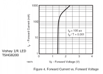
Goodie-goodieOn the other hand, take a look at this one from the spec sheet for a Vishay TSHG8200 infrared LED, picked at random for being the longest wavelength and a through-hole mount model. From a purely impedance viewpoint (ignoring noise, etc.) there’s your potential 2 ma LED.
Maybe just what we need. Time to order from Farnell again and experiment. I'd love to test this on my 407 preamp which is at 3.5mA current."Shoog, one thing to try is to run a 10mA current source (it can be a very simple one) from some positive potential to the cathode-LED junction to see if that clears things up. The voltage divider action will knock down any noise contribution from the CCS."
This is something we discussed before, and it seems a good idea. However I think the reality is that LEDs have there role at higher currents and thats where I think I will use them. In the same circuit I am using a RED LED in the cathode of a simple ECC88 CCS at about 8mA, and it works great.
I just thought everyone would be interested in the report that there seemed to be an audable distortion at lower currents.
Shoog
I just had the thought that when substituting a LED for an unbypassed resistor, you will get an increase in output (because of the smaller cathode feedback). This is something to take into account when auditioning the change, because an increase in volume is often confused with an increase in quality.
Shoog
Shoog
- Status
- This old topic is closed. If you want to reopen this topic, contact a moderator using the "Report Post" button.
- Home
- Amplifiers
- Tubes / Valves
- Ping Sy: LED for Cathode Bias