2a3 mono block powersupply
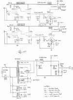
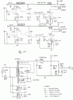
Well IM ready to build but before I spend $500.00 for a pair of plitrin output xformers I have one more question. The desiagn attached is the stereo version I assume If i leave the choke and capacitors the same the b + will be higher in a mono design. Is this a concern?
Thanks Jeff
Well IM ready to build but before I spend $500.00 for a pair of plitrin output xformers I have one more question. The desiagn attached is the stereo version I assume If i leave the choke and capacitors the same the b + will be higher in a mono design. Is this a concern?
Thanks Jeff
Attachments
It might be a little higher, so maybe a slightly lower voltage transformer would be a good idea. You can always use a 5U4 or 5Y3 rectifier instead, they have a higher voltage drop than a GZ37 or GZ34.
Otherwise, increase the cathode resistors on the output tubes a little, or get sovteks and run them HOT!
Otherwise, increase the cathode resistors on the output tubes a little, or get sovteks and run them HOT!
Here goesSHiFTY said:Otherwise, increase the cathode resistors on the output tubes a little, or get sovteks and run them HOT!
Hi tenderland,
For a single channel (mono) we want ~300V at 65mA. Hammond make a 275-0-275 transformer - 270EX (but you'll need a filament transformer for your 2A3, I used 166L2 on mine). Using that transformer, and 5U4-G rectifier (GZ37 is a bit hard to find), 10uF Solen -> 100mA Hammond choke -> 100uF Nichicon Muse, we will get the 300V we want.
You can download PSUD from Duncan Amplification website to verify.
Cheers!
wow
Thanks Arnoldc , very helpfull , was looking at the Plitron powerxformers and couldnt even come close I do like the plitron chookes though
plitron chokes
I will download PSUD and check it out , thanks again , big help
Thanks Arnoldc , very helpfull , was looking at the Plitron powerxformers and couldnt even come close I do like the plitron chookes though
plitron chokes
I will download PSUD and check it out , thanks again , big help

PSU II design question
I am trying to model the attached scheme only in a mono configuration. I am using PSU and for some reason it seems the output voltage is not correct.
power xformer = Hammond 270 ex 275 volt ct @ 125 ma
Im not sure what to use for source resistance i tried 2.2k ohm
im using a Full wave bridge using a 5u4-g
L1 = 10 H @ 50 ohms
C1 = 1000uf wkz Black gate ESR = 1/10 ohms
R1 i used 5 k ohm
I attached the origainal print "stereo version"
Help
Attachments
Hi Jeff,
Do not use a resistive load. Change it to constant current and put in 65mA (the 2A3 in the diagram already draws around 62mA).
Also when modelling for tube rectifiers, make sure that you don't exceed the maximum value for capacior input design. THe limit is on the tube rectifier manual.
Cheers!
ps.
What I suggested will include CLC
10uF -> 100H -> 100uF
PLate curves
Well the stereo ver has 245 V on the plate of the 2a3 I assume the the mon as described will have about 300 , after looking at the plate curves this is a huge difference in plate current . Im just spooked out about using sucj a lower plate voltage , after doing a search seems that lower plate voltage increases distortion. ANy input ?
Thanks J
Why are we modelling a PSU for mono and you mentioned Stereo?
If you made a PSU for mono and use it for stereo then it's not obviously going to give you the right voltages. There will be twice the current draw.
What you wanted is 250Vp which is the voltage you measure on the plate of the 2A3, minus the voltage you measure on the cathode of the 2A3. Example, if you have 300V on the 2A3 plate, and 50V on the 2A3 cathode, that gives you 250Vp and that's perfect. If you have 50V on the cathode and are using 880 ohm cathode resistor, then your current is around 56mA.
- Status
- This old topic is closed. If you want to reopen this topic, contact a moderator using the "Report Post" button.
- Home
- Amplifiers
- Tubes / Valves
- 2A3 monoblock power supply


