http://www.cc.jyu.fi/~svhiippa/Technics.pdf#search='class%20aa%20amp'
Looks like they used mosfets and bjt's concurrently.
Looks like they used mosfets and bjt's concurrently.
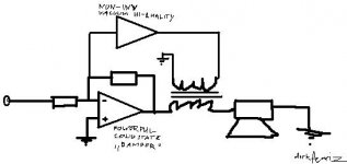
Here is a version with FeedForward ErrorCorrection (FFEC) and Hawksford feedback style error correction ( HEC).
The R6/R5 HEC feedback from the Tube Amp tells the SS amp it is not sounding enough like a tube amp, so fix it man!
But the "fix it" signal to the SS amp is adjusted to less than unity fixup so as to avoid loop instability (around R6, SS Amp, R2/R1, Tube Amp to R6 again). The feedforward path thru the xfmr then fixes the residual error by FFEC. Some gain tweeking will no doubt be required to get this all to work correctly.
Don
Attachments
My schematic in post #8 needs another fixup. The R2/R1 ratio needs to be the SAME as the R4/R3 ratio, so might as well use the same resistors (as Darkfenriz has shown in his diagram). Then the tube amp stage needs to be specified as unity gain when the xfmr. ratio is included (rather than a high op amp like gain) to compute the feedforward error correction. I was too eager to get some power from the tube amp stage also.
Similarly, the feedforward EC combined with feedback EC schematic in the previous post needs to have R2/R1 = R4/R3, so can combine them here too. Here, the xfmr ratio needs to be lowered some further so as to put less feedforward correction into the output since the SS amp is already correcting some of the problem via R6/R5 feedback.
Don
You'll need AAA if you have one of them installed in your car! 
I think this:
http://www.diyaudio.com/forums/showthread.php?postid=240542#post240542
may be an easier way to get tube sound from a SS amp. No output xfmr required, and gives the sound of a single tube too. Simpler.
Don
I think this:
http://www.diyaudio.com/forums/showthread.php?postid=240542#post240542
may be an easier way to get tube sound from a SS amp. No output xfmr required, and gives the sound of a single tube too. Simpler.
Don
smoking-amp said:My schematic in post #8 needs another fixup. The R2/R1 ratio needs to be the SAME as the R4/R3 ratio, so might as well use the same resistors (as Darkfenriz has shown in his diagram). Then the tube amp stage needs to be specified as unity gain when the xfmr. ratio is included (rather than a high op amp like gain) to compute the feedforward error correction. I was too eager to get some power from the tube amp stage also.
Similarly, the feedforward EC combined with feedback EC schematic in the previous post needs to have R2/R1 = R4/R3, so can combine them here too. Here, the xfmr ratio needs to be lowered some further so as to put less feedforward correction into the output since the SS amp is already correcting some of the problem via R6/R5 feedback.
Don
Yes, absolutely agreed, the error must be precisely subtracted, so gain must be 1.
And solid state amp must NOT be so-called 'current feedback' if one wants to use the same resistors in feedback path.
Vacuum state amp. doesn't need to be 10W in my opinion. For 100W transistor amp. 1W of error is most probably a worst case situation.
regards
"Vacuum state amp. doesn't need to be 10W in my opinion. For 100W transistor amp. 1W of error is most probably a worst case situation."
Hi Darkfenriz,
Yes, I just wanted the 10 watt figure for the for the 1st design where the amplifier powers were summed (for R2/R1 adjusted a little above R4/R3). Correcting errors only is pretty light duty in the later designs.
Would be nice though if their power could be combined more readily in the error feedforward case. Hmmm, lets see. If the R2/R1 were set a little higher than the R4/R3, and the tube amp stage/xfmr were the same gain as the SS amp gain (set by R4,R3), I guess it would add whatever correction required to get the larger output. Must be some simple way of setting up the feedbacks to get this, we are just making the SS amp look like it is always too low in gain, so needs heavy duty correcting. This would probably noticeably compromise the accuracy of the error correction though.
Hi Rlaury,
Douglas Self in his book "Self on Audio" page 293, discusses a naming convention for combined output stages. We would be talking about class A+A using his convention. I don't think there is any restriction to push-pull topology in his convention, but obviously the Technics version is P-P.
Don
Arrrgh... I think I still don't have the schematic right for the feedforward case (post #8 and later). Here is another try (attached):
R6 is optional for feedback error correction mode too, and would require reducing the feedforward correction gain (R2/R1) to keep overall unity error correction. (ie total error correctives equal and opposite to error detected)
Also, the loop gain around the top amp and R6/(R3||R4) must be kept below unity to avoid oscillation.
( I would suggest that anyone attempting to implement these later error correction schemes, first consult an article or book on the subject! )
By the way, I don't think these later error correction schemes are likely to give "tube sound", just low distortion. The first ordinary feedback scheme might do it though, as long as the SS amp is not inserting high order harmonics from crossover distortion.
Don
Attachments
The R6 option in the above schematic won't work for Error Feedback Correction because the R3,R4 node contains a small amount of actual signal besides the minus difference error term. (normal NFB operation of the bottom ampl., R4,R3, leaves a small signal component to be amplified plus the negative error term to cancel out most of the internal distortion.
Error Feedback Correction works by increasing the minus error difference alone, so as to overcome the finite open loop gain limitation of the main amplifier. But here, we would just end up increasing the total output signal of the bottom amplifier due to boosting the small signal component too. (its internal distortion removes the minus error component)
Taking the signal from the R3,R4 node should be OK for the Feedforward channel since it presumably is "clean" so it WILL correct the error of the bottom amp plus add a little bit of signal.
To make the Error Feedback Correction option work correctly, we need a PURE error difference, without the signal component. So a true differential amplifier for the top ampl. would be needed to implement this. Getting too complicated now to draw up, but should still be do-able.
Just a note for anyone attempting any of these compound amplifiers. When adding 10 Watts say to a 100 Watt main amplifier, it takes less incremental voltage to get to 110 Watts than it would take to do just 10 Watts. So the output xfmr in these designs requires a lower secondary impedance than the load impedance.
Here is the formula:
W = main amplifier watts
w = corrector amplifier watts
RL = load Ohms
Z = xfmr secondary impedance required for corrector amp.
Z = RL* (1 - SQRT(W/(W+w) ) )
SQRT( ) is square root function
* is multiply symbol
So for the 1st schematic with W = 100 watts, w = 10 watts
and RL = 8 Ohms, the xfmr needs a secondary Z of 0.37 Ohms
For W=100 and w=1 with RL=8, xfmr secondary Z comes out as 0.04 Ohms
A standard 8 Ohm xfmr secondary on the tube amp section clearly won't work for this.
Don
- Status
- This old topic is closed. If you want to reopen this topic, contact a moderator using the "Report Post" button.
- Home
- Amplifiers
- Tubes / Valves
- Class Double A