Hmmm... One tube or two tubes? Phase inverter? Soom kind of schematic?
Interesting point though, class A push pull could be interpretted as a composite class A+A double SE stage.
There was some talk in the past about combining two, out of phase, SE stages at the secondaries. This would still give even harmonic cancellation just like ordinary P-P.
Don
Interesting point though, class A push pull could be interpretted as a composite class A+A double SE stage.
There was some talk in the past about combining two, out of phase, SE stages at the secondaries. This would still give even harmonic cancellation just like ordinary P-P.
Don
Hi el' Ol,
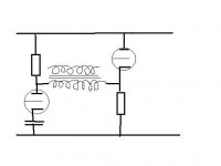
Looks like it could work, and it would be a SE design. (needs a resistor across the cap on the left tube for DC current) Never seen anything like it before. Would require a larger voltage signal on the cathode follower grid, perhaps using a tap on the load resistor of the driver tube to get both grid signals. For efficiency, I would put inductors in place of the boxes. A capacitor in series with the xfmr primary would keep DC current out of the xfmr. A low Rp tube on the left side would be desirable to match the low output impedance of the cathode follower on the right side. Since low Rp tubes tend to be low Mu, its grid drive would need to be large too, so coming closer to the other grid drive.
Practically speaking, the topology appears to offer larger voltage swing on the output, but tubes generally have plenty of this capability already. Lower impedance xfmr primaries are usually more desirable for bandwidth.
The Circlotron circuit puts two tubes in parallel (at least for class A), if somehow we could adapt your uni- phase drive idea to it. Unfortunately it would appear to require a P channel tube on one side. But a P-Mosfet or P-Mosfet/Tube cascode could be used. See attached diagram of SE Circlotron:
Note added:
I think the tube's grounded grid could be AC connected to a tap on the xfmr primary (same side) to get identical amplitude drive signal requirements for both drive inputs so they could be connected for a single drive signal input.
Also, I should note that this single ended drive Circlotron is NOT likely to sound like a typical SE amplifier, since it is using P-P type currents in the two class A drive devices. Even harmonics will tend to cancel out here.
Hi Darkfenriz,
I agree that a low output impedance would be desirable for the corrector amp. Especially if combined with a Silicon amp with nano-Ohm output Z. (OK, milli-Ohm output, just kidding).
The use of the very low secondary Z output transformer (per calculation in post #19) would likely be sufficient though already.
Lets say the 1 Watt tube amp has a nominal damping factor of 20 with an 8 Ohm load xfmr (so 8/20 = 0.4 Ohm output Z). Using the 0.04 Ohm output Z xfmr (post #19) for use as a corrector amp to a 100 Watt amp, its output impedance would drop by a factor of 200, giving a 2 milli-Ohm output Z or 4000 equivalent damping factor.
Seems sufficiently low already. But no harm in lowering it more.
Don
Attachments
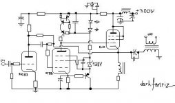
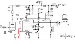
Sorry, very bad mistake.
Here's the correction, I believe it could be kind of suggestion on how to get very low impedance out of vacuum and probably Dan and you all tube gurus may kindy make some further suggestions, details improvements and so (for I basically design and build bipolar transistor class AB amplifiers, not tubes).
best regards
Attachments
Hi Darkfenriz,
Looks good to me. The CCS loaded pentode should provide lots of loop gain for the NFB to keep output Z low.
I have just been playing around with the Circlotron circuit a bit and came up with a cute stage for use as a hybrid output. Usually people just glue a complementary follower totem pole output onto a tube driver to make a hybrid amp. Then people complain that it sounds like a transistor amp.
This circuit uses grounded gate Mosfets in class A op. to maintain transparent current flow. Voltage gain is just two, so power gain is only 2. Might be of interest to someone who wants to make a higher power SE amplifier, can just tack in on. I guess it is not really too related to this class AA thread, so I will post a new thread on it.
Don
Attachments
")
- Status
- This old topic is closed. If you want to reopen this topic, contact a moderator using the "Report Post" button.
- Home
- Amplifiers
- Tubes / Valves
- Class Double A