Hi everybody,
Quite a while ago I was trying to design a new SET amplifier around a couple of 6C33Cs I've got from a Russian friend. I was wandering about a cathode follower output stage, and was facing the problem of designing a proper driver without resorting to an (expensive & bulky) interstage transformer... but eventually I ended up with another, rather "strange" idea.
It was not a cathode follower proper anymore. But it was something new (at least, I've never seen it done before by anyone) and I have been quite curious to try it out.
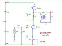
You can see it sketched in the attached picture. Without any value and component information, at a first glance it may look a lot like something well known, namely the SRPP or "Totem Pole" circuit ( hence the "fancy" name I've given to it ).
).
But indeed it is NOT an SRPP. It may still be called a "Totem Pole", but it's not one of the usual kind. While topologically it is the same, here the two tubes are completely different from each other, as are their currents.
The "lower" tube is actually just a driver, directly coupled to the output tube by means of the "totem pole" connection.
Most of the current of the output tube goes down the OPT while only a small fraction of it goes down through the driver. The resistor in the middle is high enough to provide by itself a decent load for the driver, which is thus somewhat "shielded" from load variations.
I have run some simulations and found that -while obviously having both advantages and drawbacks-, it could indeed be quite interesting.
Thus I went on and built a prototype using the 6C33 as power tube. In spite of the "random" (mostly cheap) components used and the test construction, listening room "test" results have been rather good since the very first prototype. Currently I'm still experimenting with various drivers, trying to find the best match.
I have also run a lot more simulations, with various drivers and output tubes, and have found some rather interesting "pairs". One is PCL82/6BM8 as pre+driver and EL34 as power output. More on this later.
One of the interesting thing about this circuit is that it can be used as an alternative way for implementing the "Complementary Inverse Distortion Cancellation" suggested by John Broskie on www.tubecad.com
(for that, you should use the same kind of tubes for both the driver and the output, with more than one tube in parallel for output, taking care to carefully match voltage and currents on output and driver tubes... it's kind of a mess, but can be done).
Needless to say, small & cheap tubes such as 6BQ5 / EL84 or the Russian 6C19 (low rp!) should be best for this use.
The nice thing about using the "PowerTotem" rather the the original configuration proposed on TCJ is that you are not completely wasting the current from the driver. And It also imply that you are subtracting a substantial fraction of DC current from the OPT, which will surely make it happier. (a drawback - but someone may say it's rather an advantage
  - is that you loose the 100% local NFB of the true follower output stage).
More to come... have fun!
Quite a while ago I was trying to design a new SET amplifier around a couple of 6C33Cs I've got from a Russian friend. I was wandering about a cathode follower output stage, and was facing the problem of designing a proper driver without resorting to an (expensive & bulky) interstage transformer... but eventually I ended up with another, rather "strange" idea.
It was not a cathode follower proper anymore. But it was something new (at least, I've never seen it done before by anyone) and I have been quite curious to try it out.
You can see it sketched in the attached picture. Without any value and component information, at a first glance it may look a lot like something well known, namely the SRPP or "Totem Pole" circuit ( hence the "fancy" name I've given to it
).But indeed it is NOT an SRPP. It may still be called a "Totem Pole", but it's not one of the usual kind. While topologically it is the same, here the two tubes are completely different from each other, as are their currents.
The "lower" tube is actually just a driver, directly coupled to the output tube by means of the "totem pole" connection.
Most of the current of the output tube goes down the OPT while only a small fraction of it goes down through the driver. The resistor in the middle is high enough to provide by itself a decent load for the driver, which is thus somewhat "shielded" from load variations.
I have run some simulations and found that -while obviously having both advantages and drawbacks-, it could indeed be quite interesting.
Thus I went on and built a prototype using the 6C33 as power tube. In spite of the "random" (mostly cheap) components used and the test construction, listening room "test" results have been rather good since the very first prototype. Currently I'm still experimenting with various drivers, trying to find the best match.
I have also run a lot more simulations, with various drivers and output tubes, and have found some rather interesting "pairs". One is PCL82/6BM8 as pre+driver and EL34 as power output. More on this later.
One of the interesting thing about this circuit is that it can be used as an alternative way for implementing the "Complementary Inverse Distortion Cancellation" suggested by John Broskie on www.tubecad.com
(for that, you should use the same kind of tubes for both the driver and the output, with more than one tube in parallel for output, taking care to carefully match voltage and currents on output and driver tubes... it's kind of a mess, but can be done).
Needless to say, small & cheap tubes such as 6BQ5 / EL84 or the Russian 6C19 (low rp!) should be best for this use.
The nice thing about using the "PowerTotem" rather the the original configuration proposed on TCJ is that you are not completely wasting the current from the driver. And It also imply that you are subtracting a substantial fraction of DC current from the OPT, which will surely make it happier.
(a drawback - but someone may say it's rather an advantage - is that you loose the 100% local NFB of the true follower output stage).More to come... have fun!
Attachments
Hi Paolo,
call it as you like, but you will have most serious problems to get any substantial output power out of it. The current bypass through the OPT is nothing else than a CF loaded inductively, thus the same restrictions for drive requirements do apply. I wonder how you will get the needed drive voltage swing. Efficiency must be extremely bad.
Would be nice you could supply some real world measurements.
Tom
Gluca said:Was John Broskie saying that SRPP are not that good in driving capacitive and lower loads (as a speaker can be)?
If I remember correctly, John Broskie said that an SRPP could be designed to work into just about any load, and that it should be a constant load. If the load is heavy for the devices, you simply do not get much output swing.
This is interesting, if this is true, can we redesign our SRPP for 8 ohms an do away with the OPT?

I have seen designs for SRPP OTL amplifiers using a quartet or even septet of 6C33 in MJ, they were hideously inefficient, and produced very little output power. The amplifier design in question used about 1KW to produce 40W out.. I have heard one design which was pretty anemic sounding despite the horrendous power consumption. 
IMHO designing something like this to sound good and work well is a bigger task by far than a good comparably powerful amplifier with a transformer. Of course if you like big challenges it might be worthwhile..
Incidentally you can get 15Wrms out with a single 6C33 and a 600 ohm transformer - not a bad trade off. It is not hard to build a really good opt with a winding ratio of 8.7:1 (600 ohms to 8 ohms)
ilimzn said:The fact that the tubes are different really does not make it any less of a SRPP...
Well, AFAIK "SRPP" stands for "Shunt Reguated Push-Pull", thus implying ~ symmetric push-pull operation of the two tubes. In this case, obviously there is no relevant push-pull operation to speak of. IMHO a "totem pole" can be called SRPP only if it is operating as such. That is, it must be symmetric and loaded by the proper (and constant) load impedance to allow for "push-pul" operation. Otherwise it's still a "totem pole", but if it's not behaving as an SRPP -> it's not SRPP. Again, IMHO.
In my circuit the "upper" (output) tube is working (more or less) as a CF loaded by the OPT, while the "lower" (driver) tube is working as a grounded cathode stage... the "trick" being using the output stage as (sort of) an active load for its own driver.
At least, this is how I have interpreted it. Please correct me if I'm wrong!
Gluca said:Was John Broskie saying that SRPP are not that good in driving capacitive and lower loads (as a speaker can be)?
sure it was. But /if I'm not wrong/ he was speaking about proper SRPPs (intended to be operated as such!). That is, the idea (frequently re-apparing here and there...) of using a true SRPP as an output stage to make a "push-pull on the cheap".
Actually, I guess he was (also?) arguing about the use of the SRPP circuit as a line preamplifier stage (as many indeed do, and IMHO usually with good results).
But, as said, I believe that what I've done - am doing is quite different.
PS I am currently running a mixed SRPP with an EF184 over a 6H30 (in the driver stage).
You mean that whe had about the same idea and you have built something somewhat similar to what I have done?
Wow, that would be cool! I'd be very interested about it... how is it behaving? can you post more details?
Re: Re: The "PowerTotem"... a new way to SET?
Hi Tom,
Indeed. Of course I get the voltage from the dual supply, with a relatively high negative rail... in the current prototype I have Vaa ~= 200V and Vkk ~= -300V (due to the Va max of the tubes I'm currently trying; with the previous driver with the PCL82 I was using Vkk ~= -380V).
BTW, I must say that having a small distorsion on the driver is NOT desired! This is because the distorsion from the driver can be conveniently used to reduce the overall distorsion on the output.
The real problem is finding the "right" tube, i.e. the one that fit best to give the best overall performances. I've tryed (most in simulations, some on the prototype) countless different tubes and operating points... a very few fits nicely, and I'm still seeking for the "right" one.
(more on this as soon as I'll post the complete schematic (and results) for the current prototype).
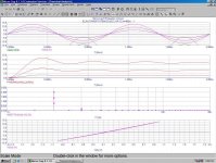
Quite the contrary. Currently I'm getting around 12W at ~ 3% THD and still a relatively nice spectrum (harmonic decay). I get this with ony 40W of dissipation (~200mA @ ~200V) on 6C33 plate (real measurements on the prototype).
BTW I'm still looking for a "better" (best suited) driver... I do belive that it is possible to do even better!
And /in simulations/ I got 10W out of a triode-strapped EL34 driven by a (triode-strapped) PCL82, which seems to be a nice fit for that... I'll post this too... but again next week, I don't have them here now.
Sure I will!
Hi Tom,
Tubes4e4 said:
call it as you like, but you will have most serious problems to get any substantial output power out of it. The current bypass through the OPT is nothing else than a CF loaded inductively, thus the same restrictions for drive requirements do apply. I wonder how you will get the needed drive voltage swing.
Indeed. Of course I get the voltage from the dual supply, with a relatively high negative rail... in the current prototype I have Vaa ~= 200V and Vkk ~= -300V (due to the Va max of the tubes I'm currently trying; with the previous driver with the PCL82 I was using Vkk ~= -380V).
BTW, I must say that having a small distorsion on the driver is NOT desired!
This is because the distorsion from the driver can be conveniently used to reduce the overall distorsion on the output. The real problem is finding the "right" tube, i.e. the one that fit best to give the best overall performances. I've tryed (most in simulations, some on the prototype) countless different tubes and operating points... a very few fits nicely, and I'm still seeking for the "right" one.
(more on this as soon as I'll post the complete schematic (and results) for the current prototype).
Efficiency must be extremely bad.
Quite the contrary. Currently I'm getting around 12W at ~ 3% THD and still a relatively nice spectrum (harmonic decay). I get this with ony 40W of dissipation (~200mA @ ~200V) on 6C33 plate (real measurements on the prototype).
BTW I'm still looking for a "better" (best suited) driver... I do belive that it is possible to do even better!
And /in simulations/ I got 10W out of a triode-strapped EL34 driven by a (triode-strapped) PCL82, which seems to be a nice fit for that... I'll post this too... but again next week, I don't have them here now.
Would be nice you could supply some real world measurements.
Sure I will!
Unimax,
I can't remember values now ... but the driver I was talking about is nothing new nor complex. A plain vanilla SRPP but with two different tubes and using a penthode as upper valve:
half 6H30 biased with RC/LED (switching back and forth) loaded with an EF184.
The screen is bypassed to EF184 cathode via a 100uF e-cap. 100R grid-stoppers.
Tubes run at 15mA (or something like that).
Signal out is taken from the lower plate (did J. Bronskie suggested it somehow?) and fed into an interstage parafeed tranny via a paper/oil cap.
I tried a regular SRPP (6H30) and later I trew in the EF184 a la Kimmel but no coupling cap. I liked it. After a while I took the output from the lower 6H30 plate instead of the upper penthode cathode. Better. Much better. Deeper, faster bass and more details.
This is not a power stage and 6H30 is looking into a high impedence load (the tranny // EF184). EF184 is just a sort of CCS there.
I saw somewhere an active (sand) load output stage ... try a search in diyaudio.
Ciao
Gianluca
Gluca said:
Signal out is taken from the lower plate (did J. Bronskie suggested it somehow?) and fed into an interstage parafeed tranny via a paper/oil cap.
thus yours is more a mu-follower rather than an SRPP...
This is not a power stage and 6H30 is looking into a high impedence load (the tranny // EF184). EF184 is just a sort of CCS there.
I see... ok, I misunderstood. We were talking about completely different beasts.
No tricks.
A typical speakers impedance is reactive as we know. The magnitude varies with frequency.
In an amp with a low output impedance, this forces the frequency response characteristic to resemble the impedance plot. ie, an impedance bump causes a response bump.
The phase also varies with the impedance. Output devices would rather not deal with this, you know, elliptical load lines and all.
In feedback amps, these variations are absorbed, but we know that a feedback loop doesn't like phase changes.
We have all heard that some speakers do/don't go well with some amps. This could be the primary reason.
If we just make our speaker resemble a constant resistance, the amp will drive the load with ease.
More or less what I was getting at was just how one would go about making a (bogey) speaker that appears purely resistive.. I know from experience that the magnepan is relatively close (and is extremely inefficient as a partial consequence) and that some horns approximate that behavior over some of their operating range, but most speakers don't remotely approximate a resistive load. (No magnepan I know of could be adequately driven by any common SE amplifier including the 845, but some larger SE amps do exist. My 30W pp 300B amps could not drive them adequately.)
OK here goes. (BTW I use a crossover sim)
A bogey (as you put it) two way will likely have an impedance peak at the crossover frequency and a rise at the top end, plus some peakage at the bottom end.
With a conventional speaker and some help from the crossover sim, an RLC across the crossover peak will level it. Fortunately, done right this corrects the impedance phase as well.
The speaker is the same, the amp sees a load which is totally resistive, and the speakers back EMF is handled by the compensation.
RC deals with the top end, and RLC or RL or two RL's can take care of the bottom end, but due to inductor size and power issues, it is wise to adapt your box to your amp or damp mechanically or something so as not to need the components. I use an RL on my back horn which has a broad peak that reaches below 20Hz and it does nicely.
Transient response is great, midrange is not harsh at all, and the amp sounds relaxed driving them.
EL34/PCL82 PowerTotem schematic diagram...
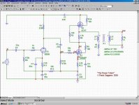
OK, let' start with the EL34/PCL82. This one can be a very simple, dirty cheap yet (I guess - no, I bet!) well sounding integrated amplifier.
Here follows the schematic diagram for the audio circuit.
I have not (yet) designed a PSU for it... but nothing very special is required. The negative rail (used by the input and driver stage) has a rather small current draw (<15mA each channel), thus an RCRC filter with sand bridge rectifier will be good enough. If you don't bother wasting some 10Watts, a CRC can be used also for the power stage (otherwise, use a CLC... remember: it's a SET, has a poor PSRR, thus you need GOOD PS filtering!). You can use the same secondary of the PT for both rails, doubling only the rectifiers ( and filters, of course ).
Heaters can be conveniently powered by AC. No matter whether you're using PCL82 (15V) or ECL82 (6.3V), you need 2 separate windings (or PTs) for the two tubes, since the driver tube heater MUST be lifted from ground down to the negative supply rail; keep the heaters some 10V more positive (less negative in this case... ) than the cathode to minimize hum and noise... but I guess I don't need to tell you these common tricks...
Needless to say, you can also try something like a 6550, KT88, etc. in place of the EL34... but be sure to optimize the circuit (and OPT) for the tube you plan to use...
'cause IME the main drawback of this circuit arrangement is probably that it can be quite picky about tubes, voltages, operating points, etc.
OK, let' start with the EL34/PCL82. This one can be a very simple, dirty cheap yet (I guess - no, I bet!) well sounding integrated amplifier.
Here follows the schematic diagram for the audio circuit.
I have not (yet) designed a PSU for it... but nothing very special is required. The negative rail (used by the input and driver stage) has a rather small current draw (<15mA each channel), thus an RCRC filter with sand bridge rectifier will be good enough. If you don't bother wasting some 10Watts, a CRC can be used also for the power stage (otherwise, use a CLC... remember: it's a SET, has a poor PSRR, thus you need GOOD PS filtering!). You can use the same secondary of the PT for both rails, doubling only the rectifiers ( and filters, of course
).Heaters can be conveniently powered by AC. No matter whether you're using PCL82 (15V) or ECL82 (6.3V), you need 2 separate windings (or PTs) for the two tubes, since the driver tube heater MUST be lifted from ground down to the negative supply rail; keep the heaters some 10V more positive (less negative in this case...
) than the cathode to minimize hum and noise... but I guess I don't need to tell you these common tricks... Needless to say, you can also try something like a 6550, KT88, etc. in place of the EL34... but be sure to optimize the circuit (and OPT) for the tube you plan to use...
'cause IME the main drawback of this circuit arrangement is probably that it can be quite picky about tubes, voltages, operating points, etc.
Attachments
- Status
- This old topic is closed. If you want to reopen this topic, contact a moderator using the "Report Post" button.
- Home
- Amplifiers
- Tubes / Valves
- The "PowerTotem"... a new way to SET?