Have you seen this amp:
http://www.shackman.reromanus.net/V-Typ-WR.pdf
Direct coupling from 400HZ.
I'm building that.
(I've also ordered a pair of cells but after 8 months no news.
I've paid 8 monts ago!)
Ciao
Guglielmo
http://www.shackman.reromanus.net/V-Typ-WR.pdf
Direct coupling from 400HZ.
I'm building that.
(I've also ordered a pair of cells but after 8 months no news.
I've paid 8 monts ago!)
Ciao
Guglielmo
") Hey, now we're talking. Thanks for help, much appreciated...
Hey, now we're talking. Thanks for help, much appreciated...I found recommended plate voltage for 6550 as 600V for push-pull class-A on www.NJ7P.org!!!
6550 is almost identical to KT88 so I guess the same goes for KT88 then... But, there is always a but, no plate curves for higher voltages...
Loading, loading, loading...
With a high resistance primary load, I'll have flatter loadline (and less distortion and power). KT88/6550 anode will then swing from 600V down to 150V and up to 1050V, ideally this is 900V swing!!
I will then need about 150V p-p of grid drive or about 55V RMS, which should be obtainable with 6C45PE or 5842 with a CCS load from diyAudio, maybe even without an CCS for starts....
Does all this sound to good to be true, you know practice and theory, Murphy's law and all that....
Finally, are there any other trade-off except for less power when using a higher resistance output transformer when driving a capacitive load???
Genious replies here will be reported directly to the Nobel science comitee
Well , in theory , DirectDrive can be more dangerous that transformer.However , i think that having 1000V swing (and limited current) from a mid-power A class direct-drive amp is not so dangerous tran 10kV swing of output transformer , plus the fact that AB power amps can deliver lots of current to it... I have had a ~2kV shock across my arms from transformer once ... Not a good feeling
Output transformer's quality is limited to core material and winding quality , so direct drive can sound better , if realised well...
Output transformer's quality is limited to core material and winding quality , so direct drive can sound better , if realised well...
Well, I totally agree with you Lukas, direct drive must be best.... and tubes swing voltage like no other + it just seems right...
Output transformers put a curtain on the sound, according to people who have done it, but on the other side line-level/small signal transformers can be very nice.... according to lots of people...
Audio reproduction must be the science that mankind has understood the least....
Output transformers put a curtain on the sound, according to people who have done it, but on the other side line-level/small signal transformers can be very nice.... according to lots of people...
Audio reproduction must be the science that mankind has understood the least....
When it comes to op-amps, and several of them in a row I get shivers down my spine, I don't know why... 
Neil S. McKean knows a lot about ESL's though...
Claims of low THD like 0,017% is not a guarantee for good sound, it's what tubes are all about, they sound better but measure worse... They are the smaritans of the electronic world
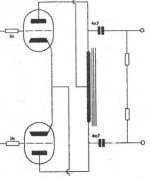
Anybody want to talk freely about using a higher resistance output transformer or choke (like in attached picture). Except for power regarding matching of primary resistance to output tubes and (thanks Brian) resonant tank circuit, I KNOW NOTHING.
In Glassware push-pull calculator the voltage swing gets better and better the higher resistance I give the choke or primary of the output transformer..... but the real world is considerably more full of trouble waiting to happen...
Neil S. McKean knows a lot about ESL's though...
Claims of low THD like 0,017% is not a guarantee for good sound, it's what tubes are all about, they sound better but measure worse... They are the smaritans of the electronic world
Anybody want to talk freely about using a higher resistance output transformer or choke (like in attached picture). Except for power regarding matching of primary resistance to output tubes and (thanks Brian) resonant tank circuit, I KNOW NOTHING.
In Glassware push-pull calculator the voltage swing gets better and better the higher resistance I give the choke or primary of the output transformer..... but the real world is considerably more full of trouble waiting to happen...
Well , i am probably incorrect with my previous statement , as there are HV tube amps with choke load.Watch
http://www.ultranalog.com/
http://www.ultranalog.com/
Well, when output tubes are seeing a choke and a capacitor, the higher the frequency the more power will be dispatiated in the reactance (inductive resistance) of the choke, I would guess....
In normal output stages, resistance of PS must be as low as possible so that the tubes couple to the load through the output transformer. In a choke loaded output stage driving a capacitor I guess power as P = I(2) x R for AC mostly is disspatiated in the choke?!?! But somehow it works, and I don't know why....
that how questions arise...
Think current, not voltage. As the frequency rises, the inductive reactance rises, so less power flows through it at a given voltage swing. But as the frequency rises, the capacitive reactance of the load decreases, so more power flows through it at that given voltage swing.
Hi,
I understand the following : as the frequency rises , current will not change much because reactive capacitance and inductance will compensate.But , the voltage drop across inductor will increase , while decreasing across capacitor ... Wee need this voltage across ESLs.
Do i misunderstand something ?
Lukas.
Thanks Sy, good point. The higher the frequency the less current and power is disspatiated in choke as power is current squared... and the more is pushed/eaten by the low capacitive resistance/reactance of the capacitor.
Well, Bazukaz do we have a common understanding
OK, enough do goody good googeling (old jungle word).
I'm designing and think I'll use the 6550, similar to KT88. This can only use 450V triode connected (as the KT88), so 1) either I use it as this 2) or I'll use the spooky pentode connection 3) or I'll have to go for 211 at low volts first. Lets have a poll from you guys!!!
Trouble is flexibility of the PS, I can get a 440V mains for reasonable price, and if I need more juice later on I can buy another one and use 2 connected in series. I ditched the voltage doubler because I can't get enough amps this way, as you probably already guessed, unless a 440V with 350-400mA comes floating by.... Gee I wish I had a grandfather running a TV repair shop....
As of now I'm designing with pSpice, luck, faith and fengshui....
Will post proper schematic next time...
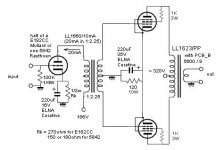
Well first stage topology.
I can use an SE first stage with an interstage to the P-P 6550 as Andrea Ciuffoli does, or I can do the normal diff pair with CCS sinks. .. better still I do both....
Anybody have some nice experiences with the SE-PP way?
Of course as an ESL fan, I like transparent, detailed sound more than anything else, so do any of these topologies tend to do anything special in this direction I'd be glad to get an opinion...
Attachments
350-400mA ... Do you really need so much ? What capacitance do you plan to drive ?
Is it per two channels , or 2x2 bridge ?In eliotts design , it uses 40mA per channel(160mA for 2x2 bridge), with a resistor load. Your design uses a choke load , so should be more efficient. I am not saying that having a more powerful supply is worse , however.
Regards,
Lukas.
Is it per two channels , or 2x2 bridge ?In eliotts design , it uses 40mA per channel(160mA for 2x2 bridge), with a resistor load. Your design uses a choke load , so should be more efficient. I am not saying that having a more powerful supply is worse , however.
Regards,
Lukas.
- Status
- This old topic is closed. If you want to reopen this topic, contact a moderator using the "Report Post" button.
- Home
- Amplifiers
- Tubes / Valves
- Small and easy ESL amp