SY said:JB favors a high B+. I reran the spectra at 15VRMS out but with a 400V B+.
How so? The datasheet says 5692's have a 100V heather-cathode rating, and I thought JB's boards used upper and lower triodes in the same tube?
This is slightly stressing them. At rest, the top cathode sits at about 1/2 the B+ (200V). So if the heaters are biased up 100V, there's no violation. Barely. Signal takes that over peak, so it's not a way I'd recommend that it be run. I'll live with a skootch of 2nd HD to run the tubes more conservatively.
In Dave Dove's pentode Aikido driving 300BXLS we are running 430V as B+. The aikido output stage is a 6N6P - so here the heaters are biased up at +120V which is fine. The pentode heaters sit at the same point and are happy so far.
The other reason for a high B+ when using it as a DHT driver is the support for output voltage swing. In the above case that can be +/- 120V. so the hign B+ is used! We have driven it that hard when filling a hall 80ft by 130ft and it stayed very clean sounding all the way through.
Nice to see the exemplory distortion figures and spectrum (such as it is) from the Aikido - it seems to confirm the listening impressions of those who have built it!
ciao
James
As SY was mentioning earlier in the thread, the most interesting figure is how well a triode performs in the Aikido configuration (ie, Aikido 1st gain stage stack) versus the same triode in grounded cathode configuration. So it would be worthwhile to do any measurement for both cases (ie, just put a high R plate resistor in place of the top tube for the grounded cathode case and a higher B+ to get the same idle current, or better yet, a CCS up top with the same idle current and B+).
Since these are distortion measurements, and so we are looking at tiny faults, I see one issue overlooked so far. The top and bottom tube sections are not exactly identical in practice.
Looking at the cathode resistors required for non identical tube types (top and bottom): R2 = R1(gm1/gm2)^.666
You don't have to use identical tube types top and bottom, a high Rp top section will get you closer to the bottom section's Mu gain. The top tube is just acting as a non-linear (3/2 power law) resistor in parallel with the bottom tubes similarly non-linear plate Rp. (so triode function is preserved, but Mu is lowered) DC biasing to get equal plate voltages may be a problem however.
So one of the Aikido cathode resistors need to be tweeked (a small variation pot and constant R setup) to minimise distortion. We need to see how much effect this trim has on distortion for a given tube. Maybe most tubes can be made very low distortion with this fix. One might be able to approach grounded cathode/CCS loading specs. (maybe even better if the two device's faults average out some) However, the Aikido stage does not operate at constant current, so one is adjusting for cancelling distortion between the R "matching" and the current variation.
Since the higher the "effective Rp" is of the top tube section, the closer the gain gets to the bottom section's Mu, and cathode to heater voltage is a big concern, we could just put a J-Fet up top. At some selected current, the J-Fet will come close to 3/2 power law (I vs Vgate from the source R) and so will preserve the triode function of the bottom device. Cathode (and Source) R values will then have to be selected for minimal distortion. Using a high "effective Rp" up top will get closer to the triodes Mu gain, and will cause less current variation with signal, so distortion null may still work out. The top J-Fet gate could have an RC bias network added, like for a gyrator, (or alternately, maybe, it's R source partly by-passed for DC biasing) to keep the quiescent output voltage (of the bottom triode) at B+/2.
Last edited:
late edit:
For using a J-Fet up top in the Aikido circuit, one needs to add a high value R from gate to drain, so that drain current varies some versus drain voltage. Otherwise you just end up with a CCS. This gate to drain R will form a voltage divider with a second moderate value resistor from the source R bottom, to give Vgate proportional to Vdrain. The overall non-linear Vgate to Idrain characteristic of the J-Fet will then mimic the non-linear Aikido top tube.
(basically a voltage controlled CCS, or a gyrator without the bypass cap)
Last edited:
Hi smoking-amp, tonight I got some results of the aikido. I wish I had the boards because I am testing from a completed unit and I don’t want to cut wires at this point! I hope that you understand and that nevertheless the distortion figures will be valuable to you.
Tested aikido pre-amplifier:
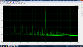
Symmetrical SRPP configuration input stage: B+ 300V, valves: 6sn7gtb n.o.s., 200R in cathodes. Bias around 8.5 to 10ma each tube.
Output stage: cathode follower, same V, same valve, same resistors same bias.
Load is 109,85K
Frequency; Harmonics relative to peak signal:
2Vrms output:
20 hertz around 0.11 %
70 Hz 0.06% distortion (THD+ noise 0.05%) increasing linearly up to 17 kHz
17 kHz 2nd: -60db 3rd: -95db
40 KHz 2nd: -66db
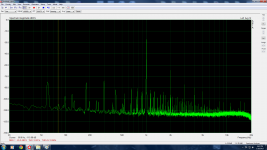
The intermodulation analysis of 2 close frequencies at 1Vrms reveals the highest distortion peak at most -60db; otherwise the levels of the first peak are kept at -65db. Nothing unusual and very clean signal.
For 2 kHz the IMD is as follow with 9.7Vrms output signal:
2nd: -54db
3rd: -69db
4th: -74db
Ear test: warm color, less detail because of the added warmth and more blending, which is coherent considering the 0.1 to 0.05 % of 2nd harmonics introduced into the music, especially at lower registers of 250hertz and below.
Note from distortion tests: there are some noise spikes in the audio band at the input volume control which is alp blue, some noise which I will try to fix, nothing major at -100 db from 0 db reference or -90db if volume is turned to maximum.
Tested aikido pre-amplifier:
Symmetrical SRPP configuration input stage: B+ 300V, valves: 6sn7gtb n.o.s., 200R in cathodes. Bias around 8.5 to 10ma each tube.
Output stage: cathode follower, same V, same valve, same resistors same bias.
Load is 109,85K
Frequency; Harmonics relative to peak signal:
2Vrms output:
20 hertz around 0.11 %
70 Hz 0.06% distortion (THD+ noise 0.05%) increasing linearly up to 17 kHz
17 kHz 2nd: -60db 3rd: -95db
40 KHz 2nd: -66db
The intermodulation analysis of 2 close frequencies at 1Vrms reveals the highest distortion peak at most -60db; otherwise the levels of the first peak are kept at -65db. Nothing unusual and very clean signal.
For 2 kHz the IMD is as follow with 9.7Vrms output signal:
2nd: -54db
3rd: -69db
4th: -74db
Ear test: warm color, less detail because of the added warmth and more blending, which is coherent considering the 0.1 to 0.05 % of 2nd harmonics introduced into the music, especially at lower registers of 250hertz and below.
Note from distortion tests: there are some noise spikes in the audio band at the input volume control which is alp blue, some noise which I will try to fix, nothing major at -100 db from 0 db reference or -90db if volume is turned to maximum.
Last edited:
Rotating new n.o.s. unmatched section tubes lead to the change of parameter of 2nd harmonics (the only one measureable vs noise floor) at 1khz/ close to 2vrms, and throughout the spectrum from:
-65db
-68.4
-64.5
-64.3
(Black glass tubes: united electron low distortion tube perfectly matched sections: -64.6db, Motorola black glass perfectly matched section -64.2db)
Two new tung-sol tubes I inserted gave a -57db 2nd (0.131%) (and -86db 3rd but is below noise level)
0.038% distortion in the best matching out of 8 tubes. Interestingly, this attenuation supplement with the best match tube was not as pronounced down from 1 kHz (-66.5db) to 250Hz (-66db). As expected the high quality valve should be placed first, then the cathode follower can be any valve it has no measured impact on THD.
Test at lower B+: Also the test suggests that with voltages of B+ as low as 120V one can get to low 0.1 % distortion with no apparent increase of harmonics except a third harmonic raising slowly as voltage decrease.
It would be interesting to see how much the distortion can be reduced with increasing B+ I will do
Last edited:
For ideal 3/2 power law tubes, the formulas give distortion free gain for the Aikido stacked input configuration. The gain is just Mu = gm1 x Rp' where Rp' is the parallel combination of Rp1 and Rp2 (top and bottom). (So Mu is reduced, to 1/2 Mu for identical tubes, but can approach Mu for a high Rp tube up top)
For the ideal tube, the Rp can be written as 2Mu/K x (Ip)^-.333, so it has no variation with plate voltage for constant current.
But for a real triode, 6SN7, say:
http://frank.pocnet.net/sheets/093/6/6SN7GTB.pdf
There IS variation of Rp with plate voltage (at constant current). See bottom graph of page 5 on the datasheet.
And the variation is such as to increase Rp as plate voltage increases. Since both tube's Rp are in parallel however (for gain computation of center point), this variation tends to cancel for small signals (one tube's plate voltage increases while the other tube decreases). For larger signals, the increase in Rp gets larger in one tube than the decrease in Rp in the other tube, but the math for paralleling them is agreeable with this for keeping constant R parallel.
So the Aikido circuit is quite impressive in removing voltage distortion from Rp.
(providing the load Z is high)
There is still variation of gm1 with plate voltage however (for a practical tube,
see bottom graph, page 5 again). (the larger variation of gm1 with current is already compensated for by the non-linear Rp's)
The gm1 error (versus plate V) should be correctable by tweeking one of the cathode resistors as long as the load Z stays constant.
Another approach would be to make an LTP or differential pair circuit using two Aikido stacks on a tail R, or CCS. This makes the currents in the two sides complementary, so the sum of the two side's gm will be approx. constant. (so removing the plate V error on gm1, due to the complementary plate Vs) A constant gm sum should then make the circuit less sensitive to the load Z as well.
Last edited:
Hi smoking! two Aikodo stacks on a CCS can be a pretty schematic.
I just wanted to thank you for the explanations of the circuit.
Actually I mixed up a little bit something in the voltage dividers and I conducted the tests at 2.7 Vrms instead of 2 Vrms. The value of RMS should be 2.7 in all figures.
The figures at 2Vrms ( sorry!) are 2db better in general. It seems that a pentode upper tube and a Mu follower configuration should give better readings at high Vrms out... your thoughts?
Last edited:
My earlier conclusion that the Aikido circuit stackup cancels the voltage sensitive distortion between the two tubes, I now believe is wrong. While the two tube's Rps do "add" (paralleled) for the gain calculation, that works because the Rps are tracking versus current. But for the voltage distortion case, they are varying in a differential manner, and a varying R divider will produce a signal.
Looks like you get 2X the error from the differential effect, but that gets divided by 2 due to the effective Rp being 1/2 of a single tube.
So the net result is the Aikido is no different from a grounded cathode stage. Other than having 1/2 the effective output Rp from two tubes. There should still be some distortion advantage in tweeking the cathode resistor value of one tube, to get the R_cathode ratio matched to the tube Gm ratio exactly.
With the cathode to filament voltage limit issue of stacked tubes, it would seem to make better sense to just use a SS Mu follower up top.
Last edited:
Your are right. When I used valves with better matched Rp from better fabrication there is a 4 to 6 db reduction in second harmonics. With normal modern valves the aikido (unless maybe you use a trimpot R divider and adjust with equipment every year) the distortion is equal to a simple grounded cathode stage.
In other words only special quality n.o.s. tubes will give a distortion advantage. This distortion advantage will not be as good as a mu follower (requiring only one tube) especially in the 3rd harmonics. Nevertheless, it is one of the best designs of all the diy audio sites imo.
In other words only special quality n.o.s. tubes will give a distortion advantage. This distortion advantage will not be as good as a mu follower (requiring only one tube) especially in the 3rd harmonics. Nevertheless, it is one of the best designs of all the diy audio sites imo.
Last edited:
Tweeking the cathode resistor can be done with switching tubes. I found the bias point a lot more interesting.
For the SS mu follower / B follower and variants tests according to your instructions, the harmonics are predominantly 3rd. There is I believe, in the aikido circuit, an advantage of 7 to 9 db of reduction of 2nd harmonics at the price (in this particular circuit using the cathode follower next stage) of higher 3rd + 15 db ( -85dbr to -70dbr) and a gain in 4th harmonics from practically 0 to - 85dbr.
What do you prefer ?
2nd -65
3rd -85
vs.
2nd -73
3rd -70
4th -85
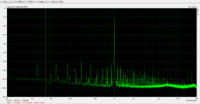
With best bias point, best circuit, best voltage I could devise the aikido produced this
2Vrms 2nd 77.5dbr 3rd -75.4 4th -81 5th 75
2.7Vrms 2nd 73.7dbr 3rd 70.1 4th 80 5th 85
5Vrms 2nd 66.5dbr 3rd -77.8 4th 92 5th 80
For the SS mu follower / B follower and variants tests according to your instructions, the harmonics are predominantly 3rd. There is I believe, in the aikido circuit, an advantage of 7 to 9 db of reduction of 2nd harmonics at the price (in this particular circuit using the cathode follower next stage) of higher 3rd + 15 db ( -85dbr to -70dbr) and a gain in 4th harmonics from practically 0 to - 85dbr.
What do you prefer ?
2nd -65
3rd -85
vs.
2nd -73
3rd -70
4th -85
With best bias point, best circuit, best voltage I could devise the aikido produced this
2Vrms 2nd 77.5dbr 3rd -75.4 4th -81 5th 75
2.7Vrms 2nd 73.7dbr 3rd 70.1 4th 80 5th 85
5Vrms 2nd 66.5dbr 3rd -77.8 4th 92 5th 80
So the net result is the Aikido is no different from a grounded cathode stage. Other than having 1/2 the effective output Rp from two tubes. There should still be some distortion advantage in tweeking the cathode resistor value of one tube, to get the R_cathode ratio matched to the tube Gm ratio exactly.
With the cathode to filament voltage limit issue of stacked tubes, it would seem to make better sense to just use a SS Mu follower up top.
On the spot: the distortion advantage in tweaking the cathode resistor of one tube to match R_cathode to Gm ratio is exposed in the post above 'with the best bias point'.
SS Mu follower is exactly what I did in the last version, it substantially reduces the -65db 2nd harmonics which is quite apparent in the listening sessions: less of that warm coating of sound.
Interesting results. I guess one is left with picking what sounds best to them in the end. If everyone is "listening" happily to some 2nd harmonic, maybe the most expensive tubes and complicated circuit are not worth the bother. Or one could intentionally "mis"-adjust the R cathode trimmer to get the sound one wants.
Makes me wonder if a clean P-P amp might successfully emulate a SE amp if a trimpot were included in one of the splitter stage loads. (I guess that only works cleanly for a class A P-P output stage with primarily local feedback though. )
Makes me wonder if a clean P-P amp might successfully emulate a SE amp if a trimpot were included in one of the splitter stage loads. (I guess that only works cleanly for a class A P-P output stage with primarily local feedback though. )
Last edited:
Makes me wonder if a clean P-P amp might successfully emulate a SE amp if a trimpot were included in one of the splitter stage loads. (I guess that only works cleanly for a class A P-P output stage with primarily local feedback though. )
I put an AC balance pot in the phase splitter in my Unity-Coupled amp and it is easy to produce a very SE-like distortion profile by purposely putting a little imbalance in there. I'll look when I get home and see if I saved any FFT captures.
- Home
- Amplifiers
- Tubes / Valves
- Survey: Aikido distortion