Pre- amp input remote control
Hello,
I'am building a tube pre-amp. I wan't to build it with a elma bbm rotary switch 6 positions, and a remote control volume, input select and on/off. For the elma switch i wan't to do the following:
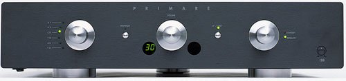
On the front of the amp it must look something like the input select of the primare i30 amp. including the led's. I have to find out how to do that. See picture
But i also wan't to be able to remote control this input selection.
My question: how can i do this. I prefer a kit or something like that. PLease help!
The schemtic of the will follow
greetings Jan Pieter
Hello,
I'am building a tube pre-amp. I wan't to build it with a elma bbm rotary switch 6 positions, and a remote control volume, input select and on/off. For the elma switch i wan't to do the following:
On the front of the amp it must look something like the input select of the primare i30 amp. including the led's. I have to find out how to do that. See picture
But i also wan't to be able to remote control this input selection.
My question: how can i do this. I prefer a kit or something like that. PLease help!
The schemtic of the will follow
greetings Jan Pieter
Attachments
Hi,
relays (not solid state) to switch between sources.
More relays to send alternative signal to other output/s eg. tape and/or remote room.
A switched attenuator (motor driven:- stepper or continuous) with extra wafer to bring in the volume leds or ganged pot using the variable output to drive an LED volume (numeral) indicator.
There is a thread for a relay controlled volume attenuator using PIC to control about 6 to 8 relays.
None of the audio signals passing through electronic switching, only through mechanical switches and preferably few of them.
I'll be watching this one. It sounds (and looks) nice and probably use some of the technology from other threads, if only we knew where to look for it.
hello,
Are there schemtics of this. Can't find them. I don't know what you mean with :" switched attenuator (motor driven:- stepper or continuous) with extra wafer to bring in the volume leds or ganged pot using the variable output to drive an LED volume (numeral) indicator."
It will take a while for the results will be seen here. I'm still building my Mono end amp. And before i begin building the pre-amp i wan't to have some schematics of how to connect all together( the amp and remote controllers i mean )
Is it possoble to this with the kits from mcs http://electronics.dantimax.dk/
Relay control isn't difficult. The volume control is harder. You either use relays in a circuit resembling an R-2R ladder or you need something akin to a uniselector from a Strowger telephone exchange. If anybody knows where to get a uniselector, that would work very nicely.
http://eshop.diyclub.biz/product_info.php?cPath=85&products_id=195
This is a kit for remote volume control and input selection. It can switch 4 sources and includes a motorized pot for volume and relays for source switching. It uses LEDs to indicate which source is selected. There is also an encoder (rotary switch type control) to select sources manually. The volume control can also be operated manually.
I purchased one of these a few months ago and it has not yet made it into my system. Too many other things going on right now. I did rig it up with some alligator clips, RCAs and some LEDs. It worked as advertised meaning it switched sources, the appropriate LED illuminated and the volume control controlled the volume.
Since it was all just laying on my bench and none of the connections from the sources to the amps were shielded there was a bit of hum but I'm pretty certain that will go away when I finally get around to putting it in a chassis and using shielded cables.
hello sherman,
I read a cople of posts on rotary encoders. But I don't understand exactly what it means. Does a rotary encoder encode the turn movement of the rotary switch that is turnt manually?
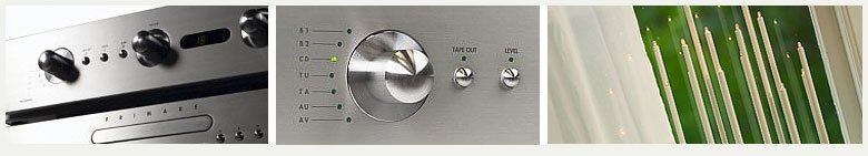
What i wan't is what you have on many hi-end amps. You can turn a manually round knob for input selection and you can select input on your remote control. I have a picture of a primare pre-amp where you can see what i mean. This must be some digital rotary control switch. Is this what you can do witch that kit And are there parts for sale that can do this?
the picture i mean is the middle one
I read a cople of posts on rotary encoders. But I don't understand exactly what it means. Does a rotary encoder encode the turn movement of the rotary switch that is turnt manually?
What i wan't is what you have on many hi-end amps. You can turn a manually round knob for input selection and you can select input on your remote control. I have a picture of a primare pre-amp where you can see what i mean. This must be some digital rotary control switch. Is this what you can do witch that kit And are there parts for sale that can do this?
the picture i mean is the middle one
Attachments
Hi, am interested in watching the ideas in this thread too. Since I've had some similar questions kicking around in the back of my mind for a similar project. (Tentatively using mercury-wetted relays for best switching quality but these tend to be expensive)
Being a bit of a newbie to the whole DIY scene myself, I'm not sure I can contribute much yet; however in a currently available book Build your own Audio Valve Amplifiers by Rainer zur Linde (ISBN: 0905705394), there are some sample I/O switching circuits (inc. PCB designs if you're so inclined) mainly Chapters 3-4 (pp. 71-108), if that's of any help should you be able to borrow a copy.
Still leaves us with the volume-control, but the above kit looks interesting.
janpieterelbaas said:hello sherman,
I read a cople of posts on rotary encoders. But I don't understand exactly what it means. ...
What i wan't is what you have on many hi-end amps. You can turn a manually round knob for input selection and you can select input on your remote control...
Basically a rotary encoder mounts on your chassis like a volume pot or other rotary switch. The difference is that it doesn't have set positions like a rotary selector switch and it isn't connected directly to the inputs. Instead it is connected to the IC that operates the relays that control the inputs.
When you turn the encoder manually it sends a signal to the IC indicating which direction you turned it. The IC then selects the appropriate input. (When you select an input via the remote the rotary encoder doesn't turn.)
For instance say you have remotely selected input number 2 on your preamp. Now you walk up to it and turn the rotary encoder clockwise. The encoder "tells" the IC, "hey, somebody just turned me clockwise", the IC then says "oh, he must want input number 3" and it activates that input.
If instead you had turned the encoder anti-clockwise the encoder would pass that info on to the IC which would then activate input number 1.
Bottom line- yes you can select your input either via the remote or by turning the rotary encoder. When the IC activates the input (turns on that relay) it also turns on the appropriate LED.
Thanks for the information. I email with a couple of kit makers. to find out if it is possible to use them together. I do have a expensive volume attenuator hat i wan't motorized with a kit from bentaudio. The man behind this site is very helpfull. And offers to customize the attenuator moter to fit it. This is expenisive for one but if he can do several then it is cheaper.
I have send a email to http://electronics.dantimax.dk/ because his kit has rotary encoders and LCD display.
Know i have to find out how to use both kits to do what i like.
Sherman: om the picture of the set you talked about i only see a volume attenuator/potmeter. So what part do i need for the manual input select that calls the rotary encoder?
greetz Jan Pieter
janpieterelbaas said:...Sherman: om the picture of the set you talked about i only see a volume attenuator/potmeter. So what part do i need for the manual input select that calls the rotary encoder?
greetz Jan Pieter
The kit I referenced includes-
* motorized pot for volume control
* relays for input selection
* IR sensor
* IR remote
* rotary encoder
So almost everything is included.
Things not in the kit-
* input or output RCAs
* LEDs
* wires to connect the PCBs, LEDs and IR sensor
* knobs for the volume and encoder
* 12VAC (yes AC) transformer for power
* mains supply cord
* fuse
* on/off switch
* chassis
It is built on two PCBs, one for the input relays and the other for the IR receiver/control unit and volume control. You need to connect the two PCBs. There are pins for standard .15" 6 pin headers (one set might be 8 pin, I can't remember) but you can also solder wires directly.
Of course you have to solder your input jack connections, the IR sensor, the LEDs, output jacks from the volume control.
You need some type of chassis but if you want to use the kit as a passive preamp it is small enough to mount in a 6" x 10" x 3" box.
If you want to use the kit with a different volume control such as a stepped attenuator I'm not sure how you could set it up. Perhaps the motorized pot could be desoldered from the board and the connections used to drive a motorized attenuator?
Do a search for "remote control"
janpieterelbaas,
Do a search of the board for "remote contrl." Already a wealth of information already available
Cheers -ALBQ
http://www.diyaudio.com/forums/showthread.php?threadid=64373&highlight=ALBQ
janpieterelbaas,
Do a search of the board for "remote contrl." Already a wealth of information already available
Cheers -ALBQ
http://www.diyaudio.com/forums/showthread.php?threadid=64373&highlight=ALBQ
progress photo
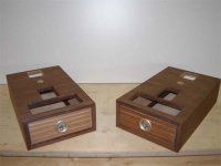
Because i ask a lot of questions i want ot show you all what i'm building. It has taken over a year to build the housing of my 300B power amp ans now it is in the final stage. Next stop is finish and solder the parts in.
After that I will start building the pre-amp. I'm still putting ideas together. It must be a mix of the looks of the power-amp, the sicties ( thinking of some plexiglass top ) and aluminium. Butt i like it to hear from other people as well what there ideas are. I'm thinking of volume knobs, feet, chassis looks anythink is welkom.
the photo of the power amp is shown below the holes on top will filled with a RVS plate. That's where the tubes will be mounted. the smaller round holes on the back are for mounting the transformers.
Comment is welkom!
Attachments
you can probably make a pretty cool remote with these programs..
www.fastavr.com with a little help from http://www.lancos.com/prog.html this page too. and just buy a generic rc5 remote from a local store..
If you got any basic cpu and basic programming language skills at all it wont be too hard..
www.fastavr.com with a little help from http://www.lancos.com/prog.html this page too. and just buy a generic rc5 remote from a local store..
If you got any basic cpu and basic programming language skills at all it wont be too hard..
Sherman said:http://eshop.diyclub.biz/product_info.php?cPath=85&products_id=195
This is a kit for remote volume control and input selection. It can switch 4 sources and includes a motorized pot for volume and relays for source switching. It uses LEDs to indicate which source is selected. There is also an encoder (rotary switch type control) to select sources manually. The volume control can also be operated manually.
Wow, that looks like a steal. Unfortunately, I am trying to go all balanced so it doesn't fit the bill for me. Since it uses relays for switching, it sounds easy to modify that. Volume might not be so easy. Would you be so kind as to read off some of the chip types it uses, if not too much bother? I can check if one of them is a volume IC and can be modified easily as well.
leadbelly said:
... Would you be so kind as to read off some of the chip types it uses, if not too much bother? I can check if one of them is a volume IC and can be modified easily as well.
Leadbelly,
The volume control is a motorized stereo 100K pot. It has a label on top that reads "8091-100KAX4". There are a couple groups of transistors. One line of 4 and one line of 5. Maybe they aren't transistors, maybe SCRs? The positions on the board are labeled Q1 through Q9.
The volume control board has one large chip on it that reads "ATMEL AT89C1 24PC 0435" (each number on a separate line). There is also a bridge rectfier and another chip in a TO220 package connected to a big heat sink. I can't read the number on it.
The input board has six relays and no ICs.
The volume control board is the "control board" and it connects to the relay board with .15" headers, one 6 pin and one 7 pin. The volume board also has the connections for 12VAC, the IR receiver and the stepper.
Sorry for the poor description!
HTH,
Sherman said:Sorry for the poor description!
HTH,
No, that's a great description, thanks! It sounds like it would be very possible to convert it to balanced, but would take a bunch more relays and some volume chips. I'll have to muse over that one
") Thanks.
Thanks.- Status
- This old topic is closed. If you want to reopen this topic, contact a moderator using the "Report Post" button.
- Home
- Amplifiers
- Tubes / Valves
- Pre-amp input remote control