Hi all,
I recently built p2p a Aikido linestage, since I didn't like the behaviour of my Lite LS-32 tube preamp (with 6H30).
Having a bunch of NOS Mullard E88CC and CV2492 (that should be e88cc special quality) I wired it for novals.
B+ is 220V (regulated with "The Last PAS" PCBs by Jackinni), then a RC network from the stabilizer to each channel B+ (150 Ohm - 10 uF MKP, I also tried bypassing the R but things didn't change)
Kathode resistors are 330 Ohm (current about 8 mA ) on both stages.
Heater is lifted from ground (about 70Vas per Bas' PSU schematic)
The problem is that using a low gain amp I hear some (acceptable) noise but if I use my "My Ref" its higher gain makes this noise quite louder and not very enjoyable (especially when listening at low level).
This noise is independent from the potmeter position and is a kind of thermal noise to my ears.
I tried tube rolling and found the tubes in the first position to be the most sensitive, the CV2492 seemed to have a slightly lower noise but showed a quite high microphony, so I ended up in a all e88CC Aikido.
What can I do to lower the noise?
After all I don't need all that gain (I never go over 9-10 o'clock) , so I already thought about using a lower mu tube in input, but the tubes I have available are:
-1 pair 6SNTGTB NOS from RCA -> different socket and needs 300V b+
-Some Mullard E182CC -> Different pinout
-Some E88C Philips Sq (single triode and mu too high)
Thanks
Andrea
Hi all,
looking with my scope couldn't detect a oscillation, but will try again.
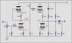
Grid and Cathode stoppers are present (if I understand correctly, grid stoppers are the 300 Ohm connected to the grids and the others are the 430 Ohms in the image taken from tubecad.
My technical language is't so complete.. what do you mean with "lead dress" ?
Cheers
Andrea
looking with my scope couldn't detect a oscillation, but will try again.
Grid and Cathode stoppers are present (if I understand correctly, grid stoppers are the 300 Ohm connected to the grids and the others are the 430 Ohms in the image taken from tubecad.
My technical language is't so complete.. what do you mean with "lead dress" ?
Cheers
Andrea
Attachments
Now daughter sleeps so...
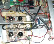
... I could take a pic of my setup.
A brief description:
- the green pcb is the voltage regulator
- the layout if the 2 channels is mirrored to have gnd in the middle
- the screw terminals on the linestage are for the filaments
If needed I can take closer photos.
About the noise it seems a kind of white or pink noise, it doesn't have a particular pitch and I couldn't get my scope to catch anything periodic....
Cheers
Andrea
Attachments
first rule-all shielded cables can be grounded on just one end;
second rule- pcbs like yours can sometimes influence sort of hum or noise augmenting via unused copper dots;try ,even if this look like major PITA - to ground as much you can of these unused surrounding Cu dots; don't make circle,you'll induce ground loop;
tips for grounding layout: always use star grounding scheme or look at Susumi Sakuma's site for other (also good) approach
I believe Andrea's concern is thermonic noise, intermitent hissing and static-like that does not vary with the volume control. I have it on my Aikido. It may be on one channel only then the other. Changing tubes does not effect it. I've resoldered and have probed all points with a wooded probe and cannot find the source. There is no hum or buzz though. I hate to admit it but a good bang on the chassis will make it stop for a while. Perhaps I should trace it backwards thru the circuit with my oscilloscope.
Perplexed,
dr._sleep
Perplexed,
dr._sleep
Here it is:
http://www.diyaudio.com/forums/showthread.php?s=&threadid=64915&perpage=10&highlight=&pagenumber=1
Notice that also Bas proposed a unregulated supply for the Aikido.
Cheers
Andrea
http://www.diyaudio.com/forums/showthread.php?s=&threadid=64915&perpage=10&highlight=&pagenumber=1
Notice that also Bas proposed a unregulated supply for the Aikido.
Cheers
Andrea
What ratio did you calculate for the noise divider?E88CC
The aim was just to get a board out there that would minimize errors for first time tube builders and have a generic psu board that could be adapted to the needs of builders (wrt to their transformers / loads etc..Notice that also Bas proposed a unregulated supply for the Aikido.
Hi Bas,
I used initially 100k and 100k, then tried 1/33 + 1/2 (106k lower resistor, 100k upper) but things didn't change.
The noise I hear is more a hiss (white-pink noise) than a ac-related hum.
Should I use grid stoppers even in the upper first tube and in the lower second tube?
Cheers
Andrea
I used initially 100k and 100k, then tried 1/33 + 1/2 (106k lower resistor, 100k upper) but things didn't change.
The noise I hear is more a hiss (white-pink noise) than a ac-related hum.
Should I use grid stoppers even in the upper first tube and in the lower second tube?
Cheers
Andrea
Hi Andrea,Should I use grid stoppers even in the upper first tube and in the lower second tube?
It certainly is worth trying. Remember to solder the grid stopper as close to the pin as possible.
like ----RRRRRpin
instead off
------RRRRR-------pin
hope that makes sense
Regards,
Bas

- Status
- This old topic is closed. If you want to reopen this topic, contact a moderator using the "Report Post" button.
- Home
- Amplifiers
- Tubes / Valves
- Noise on Aikido output