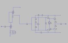
DoomPixie said:ok.. new schematic, hopefully there arent any errors in it.")
You have the VBE transistor shorted , you need one cap from the tube to the collector and another cap to the emitter of Q1 (the VBE transistor).
i just did that liek you said and the resistor (R03) burns out.. tried it twice.. changed back to the single cap and it runs again? :S could Q1 be fried?
the tube stage is exactly as it is in that diagram now.
EDIT: forgot to mention it made a loud buzzing / screaming sound straight away when i turned it on and before i managed to turn it off R03 had burned out.. after i changed back to the single capacitor and replaced R03 it runs again..
Owen
the tube stage is exactly as it is in that diagram now.
EDIT: forgot to mention it made a loud buzzing / screaming sound straight away when i turned it on and before i managed to turn it off R03 had burned out.. after i changed back to the single capacitor and replaced R03 it runs again..
Owen
i replaced the two drivers with BD139/140 and it seems to run with the two capacitors now.. it is getting better.. at full volume the sound is almost perfect now! and it makes sound with the volume lower than it used to, but it still needs some work, i will work on the css and current sink tommorow and then i will add a stage.
Owen
Owen
Hi Owen,
Now that you've got beyond fire and fuses, it's time to fix you bias circuit.
Ilimzn is quite correct in saying yours has a problem. Put the variable control in the B-E leg. If it goes open or has a bad contact, the bias will drop to zero instead of going wide open. Include a series resistor to increase the usable range (by excluding the cutoff region).
-Chris
Hi Chris,
i'll have a look at the bias circuit tommorow, it isnt MY bias circuit.. the entire output boards are from a fisher amp, i cant take any credit for their poorly designed bias circuit.
When i add the CSS and Current sink should i use variable resistors in them so that i can adjust the current? Or roughly how much current should i set it up for?
With the amp on full volume It is surprisingly good sounding amp at the moment, no doubt it's sound will change but hopefully for the better. it is already my favorite amp, it's just a shame it only works at full volume..lol
Many Thanks,
Owen
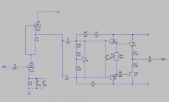
EDIT: Added updated schematic
i'll have a look at the bias circuit tommorow, it isnt MY bias circuit.. the entire output boards are from a fisher amp, i cant take any credit for their poorly designed bias circuit.
When i add the CSS and Current sink should i use variable resistors in them so that i can adjust the current? Or roughly how much current should i set it up for?
With the amp on full volume It is surprisingly good sounding amp at the moment, no doubt it's sound will change but hopefully for the better. it is already my favorite amp, it's just a shame it only works at full volume..lol
Many Thanks,
Owen
EDIT: Added updated schematic
Attachments
Hi Owen,
You are set up for 1.7 mA now, so keep it the same With the extra gain stage you could drop that to 1 mA and have lots left over. I wouldn't worry about making them adjustable. Use an LED reference for you current source to make life easy (1K2 emitter resistor).
-Chris
You are set up for 1.7 mA now, so keep it the same With the extra gain stage you could drop that to 1 mA and have lots left over. I wouldn't worry about making them adjustable. Use an LED reference for you current source to make life easy (1K2 emitter resistor).
-Chris
And BTW your 47uF output cap is NOT ok unless you are driving just a tweeter with it. For an 8 ohm load it presents a high pass at 423Hz. So, this amp would hardly be capable of bass.
You also need to check bias of the output stage, you can completely disconnect the tube stage for this. Tell us what voltage you measure on the output transistor emitter resistors.
The screeching sound you get is probably a combo of oscillation and one of your original BC drivers going into secondary breakdown when the input cap is charged, but I would bet on oscillation as being the original culprit. You may be missing an output Boucherot cell or Zobel network. Start with the first for now, 10 ohms 2W in series with 0.1uF together in parallel with output. This is only a quick and dirty thing, it will need proper implementation later. This may have been present in the original amp, just not on the amp board (usually it's somewhere near the protection circuitry ir even on the output posts).
You can test your output stage by conencting your source to the input cap, instead of the tube stage. The amplitude will be very low but you should hear undistorted sound if all is well. Before you get to that point, I don't hink it makes sense to connect the tube stage.
Chris,
Won't you need a timed relay between the output of the tube section and the amplifier section? Or am I mistaken here?
Wouldn't you want the bias transistor (all plastic case) on top of an output transistor to track the heat?
What if you incorporated an AIkido stage as your front end and used the noise cancelling factor in your favor before coupling to the output stage? Would that work any better?
Hi,
I have disconected the tube stage and tested it as you say and it does work.
Should i check the bias before or after i move the bias pot and add the css and current sink?
I know the 47uF cap is no good, i just put it there because it was all i had to hand and it did a good job of filtering out the dc offset before i realised i had missed a resistor out of the circuit
I checked the original amp and sure enough there is a cap and resistor in parallel with the outputs, So I'll sort that out now.
many thanks,
Owen
Hi Joe,
-Chris
Yes, absolutely! One of my beliefs is that when you turn the amp off, the entire thing should be off. The output from the tube circuit will have dramatic voltage swings as it comes on line and settles down (from a semiconductor standpoint). It needs to be disconnected until it all settles down.Won't you need a timed relay between the output of the tube section and the amplifier section? Or am I mistaken here?
Yes, pretty standard stuff. It goes without saying in my world.Wouldn't you want the bias transistor (all plastic case) on top of an output transistor to track the heat?
I don't think it would Joe. That's because I believe in voltage regulators. Kill the noise at the source instead of running it all through your amp. I use series regulators, against the current (sic) fad.What if you incorporated an AIkido stage as your front end and used the noise cancelling factor in your favor before coupling to the output stage? Would that work any better?
-Chris
Hi Owen,
You can check the bias now, but it will need to be completely retested and set once the extra stage and current sources go in. You are reconfiguring the bias circuit to be reliable anyway.
Your output capacitor can simply be removed once the circuit has been stabilized. Leave something in there for right now as the circuit is under developement. If you are making a board, do not make a space for it. It will go in the end.
Remember, you are pretty much starting over, right now you have a basic circuit worked up. All normal precautions still apply.
-Chris
Hi Owen,
A previous post had an incorrect word. Instead of rectifier I intended regulator. So while you are at it, build a high voltage regulator. As an expedient, a stack of zeners will work.
A simple pass transistor (MJE340)/ single error amp (MPSA42) with a zener reference will work okay. A CCS feeding the base of the pass transistor (MPSA92) will really improve the performance. It's quiet.
You will find the output voltage has a positive temperature coefficient caused by your zener. I use a 100 V zener for this simply because a zener stack does the same thing.
-Chris
The tube stage will all be wired p2p. The power supplies each have their own PCB and transformers. The SS stuff will be on PCB aswell eventually. I havent got around to doing anything more yet, i will get it out again later and add the CSS and Current sink. Going to go and add them to the schematic now.
Owen
Owen
Hi,
Haveing some problems getting a bias reading, if i measure accross one of the emitter resistors my multimeter dosnt register anything, dosnt matter what i do with the bias pot i still get nothing, so there is something wrong somewhere unless i'm measureing it wrong?
Owen
Haveing some problems getting a bias reading, if i measure accross one of the emitter resistors my multimeter dosnt register anything, dosnt matter what i do with the bias pot i still get nothing, so there is something wrong somewhere
unless i'm measureing it wrong? Owen
- Status
- This old topic is closed. If you want to reopen this topic, contact a moderator using the "Report Post" button.
- Home
- Amplifiers
- Tubes / Valves
- Hybrid amplifier help...