In another thread, SY wrote:
I'm bothered about screen current(s) flowing thru the tail.
Does someone already built and checked one, are there special tricks ?
Yves.
Actually, my question was about using pentodes for the input tubes, since the desiradata there are high plate resistance and high mu. Seemingly, they would work better than triodes for this application.
I'm bothered about screen current(s) flowing thru the tail.
Does someone already built and checked one, are there special tricks ?
Yves.
The surefire way to remove the G2 current from the tail is to use a floating G2 supply, which is connected + end to the G2 of both pentodes, and - end to the common cathode point. However, it is a bother, not to mention capacitance coupling where you do not want it.
Fortunately, with some precautions, you do not bneed to do this.
Firstly, for Vg2 sufficiently lower than Vplate, G2 current is a virtually fixed potion of plate current. This means that in a LTP, G2 currents will also behave differentially, and you will only have a common mode error - as one pentode G2 current increases, the other's decreases. You just need to increase the tail current to account for 2xIplate + 2xIg2 flowing through the tail. Things do get complicated as plates swing closer to screen grids, current increases drastically and is not a 'fixed' portion of Iplate. Also, setting a relatively low amplification factor for the pentodes results in the common cathode node swinging up/down signifficantly enough to modulate effective Vg2, which introduces some error in expected performance.
In other words, if your pentodes are relatively high gm to begin with, and your chosen amplification factor is high, and your chosen Vg2 is low compared to Vplate, and your pentodes are well chosen so you can use the aforementioned Vg2 and Ig2/Vp relationships, you should not plan on any special measures due to Ig2, except for accounting on a constant 2xIg2 going through the tail.
TNX2U for answers.
Ilimnz,
That is exactly what I feared about.
According to your points, I'm looking for a penthode with lo screen voltage. Probably, using a common screen resistor bypassed to the cathode may be the simpler way, screen currents trying to balance themeselves except at extreme "negative" plate swing where the cap could "smooth" by providing this extra current.
ray_moth,
Looking at H.K. it seems to me that the phase splitter has so many feed back loops around it that I'm not sure if it can still be called an LTP Also, the voltage divider at the upper anode is somewhat confusing! And that 12BY7 IS really beeffy
A very curious and interesting implementation.
Still investigating,
Yves.
Ilimnz,
That is exactly what I feared about.
According to your points, I'm looking for a penthode with lo screen voltage. Probably, using a common screen resistor bypassed to the cathode may be the simpler way, screen currents trying to balance themeselves except at extreme "negative" plate swing where the cap could "smooth" by providing this extra current.
ray_moth,
Looking at H.K. it seems to me that the phase splitter has so many feed back loops around it that I'm not sure if it can still be called an LTP
Also, the voltage divider at the upper anode is somewhat confusing! And that 12BY7 IS really beeffy A very curious and interesting implementation.
Still investigating,
Yves.
What you want is often in the first stage of tube oscilloscopes. The problem is, the input voltages there are on the order of tens of mV so the output swing is not very large. The typical solution is NO coupling cap to common cathodes, G2 of both pentodes tied together, and a common Rg2.
I have a scope with that sort of input stage here. The common Rg2 is quite large - 10kOhms. Two EF184 pentodes are used (typical gm is 15mA/V). Unfortunately I cannot tell you exactly what Vg2 is as the input stage is coupled in series (!) with the 3rd stage (4 stages total) in order to conserve power - it is a direct coupled amp of course. My guesstimate be about 100V or so.
Here you can again see that the constant current of the LTP is used to an advantage. The tail current is the same for both stages that are in parallel, and includes 2xIg2 of the pentodes for the second stage. The specs say less than 2% distortion so it seems to work quite well. Also, note high Rg2, for two reasons - to use Ig2 to get proper Vg2, and also to limit G2 dissipation in an event of overload. As Vp comes close to Vg2, G2 current increases and Vg2 decreases. This also decreases Ig2 of the other leg, so there is some balancing action. Presumeably, the idea is not to work into this area of operation under normal circumstances.
Not sure if it's appropriate to gig up an 12-year-old topic, but this is exactly what I have in mind right now.
I have lots of Russian GU-17/ГУ-17 (6360/QQE03-12 equivalent) low power double tetrode with common cathode & g2, which might fit this application. I/m thinking of long tail pair with fixed (zener regulated) G2 or something similar.
Have any one tried this approach and how was your implementation/results?
Duong,
Looks interesting, can you give some further explanation of why and how to do so? What I initially planned to do was just a Zener from the G2 to common cathode.How about like this
Mona
I’ve been looking at 2 examples of pentodes in PI position (that I know of) to see how they deal with G2 supply.
- HK Citation II just use a big resistance to both G2 of the 12BY7s with no bypass capacitor. Also Vg2 is considerably higher than Va.
- Quad II (not LTP btw) use separate resistors for each EF86’s G2, but again no bypass capacitor.
Instead, they used a 0.1uF across the G2s. Vg2 is similar to Va. Personally I would prefer Va to be considerably higher than Vg2. I have also seen around here people state that Va should be higher than Vg2 an amount of at least the magnitude they want to drive (i.e. >80V if you use a pentode to drive a 300B SE).
What’s your opinion?
Cheers,
Duong
Not sure if it's appropriate to gig up an 12-year-old topic, but this is exactly what I have in mind right now.
I have lots of Russian GU-17/ГУ-17 (6360/QQE03-12 equivalent) low power double tetrode with common cathode & g2, which might fit this application. I/m thinking of long tail pair with fixed (zener regulated) G2 or something similar.
Have any one tried this approach and how was your implementation/results?
Duong,
Yes. I had to implement bias balance pot to make them even.
Here is the result: they are driving 6S19P triodes.
YouTube
I totally forgot that you did use GU-17 to drive 6S19P.
Did you use separated fixed bias for each G1 of the GU-17? Generally in traditional LTP stage (AC or DC coupled), the G1s receive a same potential to the common cathode hence not easy to adjust except varying plate load.
Did you use separated fixed bias for each G1 of the GU-17? Generally in traditional LTP stage (AC or DC coupled), the G1s receive a same potential to the common cathode hence not easy to adjust except varying plate load.
Today I also tested with QQC04-15 (5895), it turned out even harder to adjust since the tube is directly heated. Feeding filament with DC means that each half of the tube receives different Vgk (given same G1 potention), making the matter worse.
Wavebourn, can you share your idea of biasing the tube, I still have a hard time figuring it out.
Duong,
Wavebourn, can you share your idea of biasing the tube, I still have a hard time figuring it out.
Duong,
Dear Wavebourn,
I would like to use pentodes as well for phase inverter of a GU50 power amp.
It is needed approximately 60 Vp with an heavy load (I would like to apply shunt feedback from the anode of the GU50 to the anode of the PI). Do you think GU-17 can be a good phase inverter, in the configuration you used?
Thank you in advance for the information you would like to share.
Roberto
Thanks EL504,
I was looking also to 6GF5 (here the curves of the 6GE5 that are very close: http://www.r-type.org/pdfs/6ge5.pdf ) even if they need more feedback to become linear, but can survive to really high plate voltages.
I was looking also to 6GF5 (here the curves of the 6GE5 that are very close: http://www.r-type.org/pdfs/6ge5.pdf ) even if they need more feedback to become linear, but can survive to really high plate voltages.
In another thread, SY wrote:
I'm bothered about screen current(s) flowing thru the tail.
Does someone already built and checked one, are there special tricks ?
Yves.

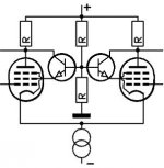
Yes I have built a 120W amp with pentode phase invertors very recently. I got round the screen inbalance to some extent by using a resistor rather than a voltage to supply the screen. This forces the currents in the two screens to be more closely matched. The 2xNPN idea I saw earlier is very clever on returning the screen current back to the plate. However I did match valves for the same plate voltage. Q1 is a high voltage transistor not BC548 before anybody spots this.
You can get a lot of gain in the LTP which reduces the demands on the first stage. They can also be very linear don't have miller effect problems.
Last edited:
- Status
- This old topic is closed. If you want to reopen this topic, contact a moderator using the "Report Post" button.
- Home
- Amplifiers
- Tubes / Valves
- Long Tail Pair Phase Inverter with Pentode?