Ive just completed the amp today!
It appears to be working, but not very much volume at all, quite faint.
The left channel seems weaker than the right also.
Im yet to connect to my signal generator and scope, but ive just tested with music playing through my phone.
Only difference ive made to the original schematic is ive made it ultra linear, and i have wired the grids to the centre tap on the transformer.
Attachments
![20170827_134841[1].jpg](/community/data/attachments/584/584337-a2d44cad91455d7daa3b6585163fcb0e.jpg)
I thought i was supposed to be getting 3 watts per channel, but anyway ive tried more tracks and as usual, alot of these are quieter than others, the volume is not too bad, but would like it better.
Ive seen many old stereograms with the ECL82 in Class A operation with much louder volume than this.
Perhaps it is the speakers?
IDK, they are Yamaha home theatre speakers and are rated at 40W.
I also see the impedance is 6 ohms.
Anyway, there is an issue with the left channel, dont know what the problem is yet, but its very distorted and low volume.
I had a similar issue when I built my ECL86 (with ultralinear OP). It turned out that there was insufficient clearance between the output transformer wires and the triode grid connections on the right channel; a ultrasonic oscillation was the result, with the exact same symptoms you describe. Are the ECL82 tubes new or are they a pull from old equipment? I've got a few ECL82/ECL86 based stereograms on my collection, and almost all of them had weak output tubes.
A 40watt speaker is most likely around 85db/watt sensitivity. The sort of speakers found in these old consoles would be about 100db/watt. Thats a huge difference.
If you want to get the undoubtedly great sound these little valves are capable of, you are going to need to build some high sensitivity speakers using some of those old console drivers, which work best in open-baffles.
Shoog
If you want to get the undoubtedly great sound these little valves are capable of, you are going to need to build some high sensitivity speakers using some of those old console drivers, which work best in open-baffles.
Shoog
The tubes are NOS philips tubes all test as new.
I was playing around with it again and it turns out that one of the speakers is faulty as i swapped rhe connections over and its giving the same fault on rhe the other channel.
Would any ultrasonic oscillations show on a scooe easily enough? Im going to scope it tomorrow with a 1000hz sine wave.
It is my intention to get some nice full range speakers with high sensitivity. They dont seem easy to find.
I think there was some suggestions here about modifying it to use negative bias. Would this make much improvenment in this area? Is there anything i should change in this schematic if im using UL configuration?
A cheap Q Acoustics 3010 2-way small bookshelf speaker is rated for 86dB and does have a pretty good volume with my 3W ECL86 SE amp. I had satisfactory results also with a B&W 685. They both have average sensitivity for this kind of entry-level speakers, I guess that other similarly priced speakers of this size will produce just about the same volume. Maybe your speakers have a exceptionally low sensitivity. This is often the case with the speakers that come with a home theatre kit. I tried the high-efficiency fullrange route with a pair of Mark Audio Alpair 12p and also with a smaller vintage Philips, but I did not liked the shortcomings; maybe I'm too used to the sound of multi-way speakers. The scope will be useful to measure the actual output power.
Full range speakers are rarely just that. Mine consists of very high sensitivity field coil vintage speakers on an open baffle coupled to tweeters over 10khz and powered aperiodic loaded woofers below 400hz. Its really rarely satisfactory to just go with a single fullrange in some sort of box.
The vintage drivers were designed for open baffles (those old consoles never had well sealed cabs) and so perform very badly in box enclosures. Modern fullrange drivers are a specialist subset of the market and as such, regardless of how they perform - they fetch a premium price for their niche market status.
Another viable option is to go with 12" PA drivers in leaky/aperiodic boxes. These can sound fantastic and be reasonably cheap.
Unfortunately if you build a flea powered amp it forces you down certain pathways to get the performance they can deliver. Remember that the standard speaker makers are designing for the average amp output of a minimum of 20watts which is at least 3 times the volume your amps are capable of delivering.
Shoog
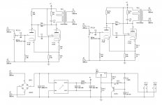
Only difference ive made to the original schematic is ive made it ultra linear, and i have wired the grids to the centre tap on the transformer.
I did not find this schematic. Can you put it here on the forum ?
Ive seen many old stereograms with the ECL82 in Class A operation with much louder volume than this.
The volume of course depends on the input signal level. How much did you feed in ?
And have you measured how much is at the g1 of pentode side ?
I did not find this schematic. Can you put it here on the forum ?
The volume of course depends on the input signal level. How much did you feed in ?
And have you measured how much is at the g1 of pentode side ?
The schematic was posted by the person who started this thread on the first page.
Ive just built an amp using this schematic.
As far as signal level goes, im only using my cellphone for testing, im going to grab my turntable and preamp to do more reliable tests with the same signal level going in.
Every audio track on my phone seems to have a different level of volume.
Have not measured the grid voltages as of yet, my multimeter died on me the other day lol
Full range speakers are rarely just that. Mine consists of very high sensitivity field coil vintage speakers on an open baffle coupled to tweeters over 10khz and powered aperiodic loaded woofers below 400hz. Its really rarely satisfactory to just go with a single fullrange in some sort of box.
The vintage drivers were designed for open baffles (those old consoles never had well sealed cabs) and so perform very badly in box enclosures. Modern fullrange drivers are a specialist subset of the market and as such, regardless of how they perform - they fetch a premium price for their niche market status.
Another viable option is to go with 12" PA drivers in leaky/aperiodic boxes. These can sound fantastic and be reasonably cheap.
Unfortunately if you build a flea powered amp it forces you down certain pathways to get the performance they can deliver. Remember that the standard speaker makers are designing for the average amp output of a minimum of 20watts which is at least 3 times the volume your amps are capable of delivering.
Shoog
Yes a true full range driver can be a hard thing to source.
TBH i agree, a standard PA speaker or something with a piezo electric tweeter added would probably do the job.
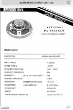
Ive just found a pair of speakers here, IDK how good they are, they are made in Taiwan, but are full range and 93dB sensititivy.
What do you think?
Here is the datasheet
Attachments
Last edited:
Quick update guys.
I decided to pull out the "faulty" speaker out of the box and the spade terminal to the speaker was loose and just flopping around!
It must have been making some contact, because it was making a very faint, crackly sound.
I soldered the wires on as the terminals were falling to bits.
Made a huge difference!
The other speaker also had bad terminals, so i soldered those too.
My question is whether or not i have done any damage to the tubes and or OT without any load?
Well there must have been some load, as there is a crossover arrangement and a tweeter inside the box, but anyway its working good now")
I decided to pull out the "faulty" speaker out of the box and the spade terminal to the speaker was loose and just flopping around!
It must have been making some contact, because it was making a very faint, crackly sound.
I soldered the wires on as the terminals were falling to bits.
Made a huge difference!
The other speaker also had bad terminals, so i soldered those too.
My question is whether or not i have done any damage to the tubes and or OT without any load?
Well there must have been some load, as there is a crossover arrangement and a tweeter inside the box, but anyway its working good now
![20170904_114843[1].jpg](/community/data/attachments/571/571251-bfc3c98d309bf8a64793ea57edfd7e7e.jpg)
also had similar problems
i had a similar issue with my ecl82 build a while back. it was SE without feedback. had all sorts of issues with hum which we killed with star grounding.
in the end changing the layout killed the oscillating style squeals n such. though the components were not really spaced to far apart. just laid out different on the small proto board. a lot of trouble comes up when you fire up a schematic. always smarter thing to do is follow a wiring layout( see pictures of successfully working amp) thats proven to perform flawlessly and then just duplicate it. the sound was not loud initially then i tried other wire taps on the tranny and it got 3 times louder. loud enough on my full range 8 inch philips speakers that are rated at 88dB..
My ECL86 SE buld still has issues. im trying a different layout. i checked if my tube got damaged. checked each in against the other with DMM. nothing showed up as shorted except of curse ping 4 and 5( filament). is there a failure mode that cannot be detected easily and happens often in new tubes.?? the amp plays loud like crazy at full gain. its like the german radios i have when played loud...crazy loud.( partly its the distortion though but its not horrible kind),,, the bad distortion is when low notes on a music score are playingits like someone deleting 0.1secondi parts of an mp3 file scratchy too like kkkkhhhrrr khrrrrrrr sound.....to be more clear i think it sound like when u connect your one speaker into an solid state amp the wrong way...like both terminals of a speaker into two different channels or something like that.
im not really worried coz i have enough of these tubes NOS but need to learn asap how to keep them from popping incase that can happen
Another thing non electrical people like me would benefit from knowing is the common error or problems in wiring or failed parts in both SE and PP amps using tubes like ECL82 /86. kind of relation between measurements and possible failed part or wiring error.. would save time if i knew this!!
BR
Amit
I had a similar issue when I built my ECL86 (with ultralinear OP). It turned out that there was insufficient clearance between the output transformer wires and the triode grid connections on the right channel; a ultrasonic oscillation was the result, with the exact same symptoms you describe. Are the ECL82 tubes new or are they a pull from old equipment? I've got a few ECL82/ECL86 based stereograms on my collection, and almost all of them had weak output tubes.
i had a similar issue with my ecl82 build a while back. it was SE without feedback. had all sorts of issues with hum which we killed with star grounding.
in the end changing the layout killed the oscillating style squeals n such. though the components were not really spaced to far apart. just laid out different on the small proto board. a lot of trouble comes up when you fire up a schematic. always smarter thing to do is follow a wiring layout( see pictures of successfully working amp) thats proven to perform flawlessly and then just duplicate it. the sound was not loud initially then i tried other wire taps on the tranny and it got 3 times louder. loud enough on my full range 8 inch philips speakers that are rated at 88dB..
My ECL86 SE buld still has issues. im trying a different layout. i checked if my tube got damaged. checked each in against the other with DMM. nothing showed up as shorted except of curse ping 4 and 5( filament). is there a failure mode that cannot be detected easily and happens often in new tubes.?? the amp plays loud like crazy at full gain. its like the german radios i have when played loud...crazy loud.( partly its the distortion though but its not horrible kind),,, the bad distortion is when low notes on a music score are playingits like someone deleting 0.1secondi parts of an mp3 file scratchy too like kkkkhhhrrr khrrrrrrr sound.....to be more clear i think it sound like when u connect your one speaker into an solid state amp the wrong way...like both terminals of a speaker into two different channels or something like that.
im not really worried coz i have enough of these tubes NOS but need to learn asap how to keep them from popping incase that can happen
Another thing non electrical people like me would benefit from knowing is the common error or problems in wiring or failed parts in both SE and PP amps using tubes like ECL82 /86. kind of relation between measurements and possible failed part or wiring error.. would save time if i knew this!!
BR
Amit
The triode section has a max current of 3.5mA and an amplification of 70, with a max plate dissipation of 1 Watt.
So 170V at 0.5mA looks about right to me.
I would also suggest trying some negative feedback. The distortion may get a bit messy in a pentode circuit like this without it. Also it provides more useable power too.
This is an excellent working point for this tubes triode. It has been proven by many other circuits to be good working. Even famous designers are choosing those values.
It isn't necessary to do 100uF on the anode of the pentode. Try 47uf, thats what good designers choose. The foil caps parallel are unnecessary if you choose good caps. No designs of the old days has used those and they sound brillant.
But remember, use dry electrolyts in the high voltage section, not the cheap wet types. They last many longer but are more expensive. The sound will be much more better.
How will this circuit perform?
I would be very concerned due to the lack of a bypass cap on the output stage.
I would be very concerned due to the lack of a bypass cap on the output stage.
Can you explain more please? i am new to tubes.
This particular circuit was assembled and demonstrated as an example of a simple and good ecl82 amp. I also have seen such a schematic from radio museum.org, Only change being that the plate to plate feedback resistor was 3.3M, whereas the new one shows 330k.Here is a short article on cathode bypass capacitors:
The Cathode Bypass Capacitor Explained - DIY AUDIO BLOG, AUDIO WORKSHOP
The lack of a cathode bypass cap in that design would make sense if it was copied from the output stage of some old AM radio, and I would assume that you are aiming a little higher than that?
The Cathode Bypass Capacitor Explained - DIY AUDIO BLOG, AUDIO WORKSHOP
The lack of a cathode bypass cap in that design would make sense if it was copied from the output stage of some old AM radio, and I would assume that you are aiming a little higher than that?
I would be very concerned due to the lack of a bypass cap on the output stage.
There is positive current feedback via the tap on the output tube cathode resistance back to the driver cathode. Pick the correct point & the output impedance of the amp is lowered. But there will be more distortion.
This connexion is sometimes used to get more gain but in conjunction with negative voltage feedback from the OPT secondary. Worked for me in a couple of circuits long ago,
- Status
- This old topic is closed. If you want to reopen this topic, contact a moderator using the "Report Post" button.
- Home
- Amplifiers
- Tubes / Valves
- Building an ECL82 Single Ended Amp ...