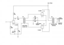
I dreamed up this design a couple of years ago and never pursued it and since I'm bored I thought I would post it and hopefully learn how to bias it into class A. As for as I can tell I need to make sure that the entire PP output voltage is biased above ground potential. If I do this will it then be biased into class A?
G
G
Attachments
CLASS A
Hi Gavin,
You already defined the operating points by defining B+ and Rk.
Rk being referenced to ground returns a negative bias voltage on the grid.
Class A1 operates the tubes in such a way that they always conduct at full current and are not affected by the passing of an AC signal.
Class B however only makes the tubes work (conduct) when a signal is presented.
I simplify this on purpose to make it more obvious.
So you will need to define the operating class in a linear manner by looking at the curves of that tubes' datasheet for a given B+ and change Rk accordingly.
Several points of operation are possible,the trick is to choose the most appropriate for the task at hand.
Since I don't have these data at hand here, it could well be your amp is already operating in class A.
From the above explanation it should be clear that Class A is the least efficient and combining both classes to Class AB gives more efficiency at the expense of a loss of linearity.
Cheers,")
Hi Gavin,
You already defined the operating points by defining B+ and Rk.
Rk being referenced to ground returns a negative bias voltage on the grid.
Class A1 operates the tubes in such a way that they always conduct at full current and are not affected by the passing of an AC signal.
Class B however only makes the tubes work (conduct) when a signal is presented.
I simplify this on purpose to make it more obvious.
So you will need to define the operating class in a linear manner by looking at the curves of that tubes' datasheet for a given B+ and change Rk accordingly.
Several points of operation are possible,the trick is to choose the most appropriate for the task at hand.
Since I don't have these data at hand here, it could well be your amp is already operating in class A.
From the above explanation it should be clear that Class A is the least efficient and combining both classes to Class AB gives more efficiency at the expense of a loss of linearity.
Cheers,
SINCE I AM SUCH A LAZY PERSON
Gavin,
There's a wealth of info there.
http://www.radau5.ch/pdf_files/amp_2.pdf
Happy reading,
Gavin,
There's a wealth of info there.
http://www.radau5.ch/pdf_files/amp_2.pdf
Happy reading,
Hi Frank,
After looking at the curves here at work I don't think that I will be able to acheive class A at the output all the way to clipping but I should be able to acheive class A ouput with 8 volts on the cathode of each 6sn7 at lower levels. If I do away with the bypass cap on the gain stage I think that I will have better luck. Either that or use a 2:1 intestage.
G
CLASS A
Gavin,
Replacing the 6SN7 at the input with say a 6SL7 would relieve you from the expense of an IS xformer (they're not really wideband most of time anyway unless you go for a 1:1 which stands a better chance)
And while I'm looking at it,is it necessary to parafeed the IS as you present it in the circuit diagram?
Just redo the maths so you get the 6SL7 into class A op which should not be hard.
Just hope I shed some light on the operation classes for you.
Cheers,
I'm looking for less gain. Not more. The Sowter 8920 has to be AC coupled. It is a small nickel core interstage that has very impressive bandwidth specs. I need a good level of current into the phones but not that much voltage. I'll do some math when I get home. Listening to the Raiders game right now. Talk to you later.
G
G
there's an easier way.
Gavin,
If you simply use the values in the "resistance coupled amplifier" charts found in the back of any tube manual, you will be biased into Class A. Divide by 2 for Rk, since they are sharing the resistor.
I would suggest though that you could make a much easier headphone amp using the 6SN7's as cathode followers. Parallel two halves on each channel's output, and you can get a low enough output impedance to drive your phones.
I built one recently using two 6SN7's driven by a 12AY7, and I had absolutely no complaints about the sound. My headphones are a 60 ohm Sony set.
I can post a schematic with the values I chose, if anyone's interested.
Joel
RK.
Hello,
Which I would split anyway so that each tube has its' own cathode resistor and bypass cap.
The ac signal is going through the amp much faster then these electrolytics can discharge and having a common point to share them isn't a very good idea in a PP.
Cheers,
Hello,
Divide by 2 for Rk, since they are sharing the resistor.
Which I would split anyway so that each tube has its' own cathode resistor and bypass cap.
The ac signal is going through the amp much faster then these electrolytics can discharge and having a common point to share them isn't a very good idea in a PP.
Cheers,
Re: RK.
Frank, I disagree. Using a single resistor guarantees that both output tubes have the same bias voltage applied. This assists in equalizing the stage.
fdegrove said:The ac signal is going through the amp much faster then these electrolytics can discharge and having a common point to share them isn't a very good idea in a PP.
Frank, I disagree.
Using a single resistor guarantees that both output tubes have the same bias voltage applied. This assists in equalizing the stage.DISAGREEMENT
Joel,
I sort of thought you might.
That is all very well in theory but the fact that one uses one common R and bypass adds other sonic artefacts that can be avoided by giving every tube a cathode resistor + cap of its' own.
No two tubes are exactly the same and they don't age the same way either.
Doesn't cost an arm and a leg to try out anyway.
Give it a try Joel,why not?
Cheers,
I'm definately interested in seeing a diagram of your amp Joel. I just thought that it would be interesting to see what a transformer coupled Push Pull class A headphone amp would sound like. I may still do it one day. This was something that I threw down one rainy day and never really looked at the diagram again until yesterday. Oh, the Sowter transformer in the diagram is an intput/phase splitter transformer not really a true interstage. I'll play around with the diagram and the numbers as soon as I get enough time and post the results. It may make an interesting project one day.
G
G
- Status
- This old topic is closed. If you want to reopen this topic, contact a moderator using the "Report Post" button.
- Home
- Amplifiers
- Tubes / Valves
- Biasing Push Pull Triode amp into Class A