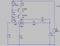
Anyone tried something like this ?
I plan to build it for a friend of mine who insists on having the gain adjustable.
How the anode follower compares to cathode follower in terms of sound ?
Other than low input capacitance any other comments please ?
Mic
I plan to build it for a friend of mine who insists on having the gain adjustable.
How the anode follower compares to cathode follower in terms of sound ?
Other than low input capacitance any other comments please ?
Mic
Attachments
long time ago invented ")
anyway-next time try to mark output load little different,in this case I just presume that your load is 47K?
in most cases,difference in sound between different stage topologys is more dependant of actual physical layout ;
speaking of same tube ,naturally
for anode follower ,tube with lowish Ra is preferred,even more than for cathode follower;
but I think that EC99 will do the job
edit-some of Audio Inovations preamps used that config,little Rafael from Germany too ,and they are pretty good judged in hifififi journals of this era
I tried that once,with ECC82 and I pretty liked the sound;
but with my overcomplicated shunt reged supply of that time
Seely, in Electron-Tube Circuits (1950) covers an equivalent circuit for it on p.108-111; and points out that the anode-follower's output impedance is approximately twice that of the C.F.
However the input impedance will be much lower. It is phase-inverting.
TCD covers it at least once.
And there is a paper, introducing The Anode Follower from Charles P. Boegli, (Audio, Dec. 1960) in PDF format.
I'm sure it must have had some discussion on this forum at sometime in the past too.
I can't comment on the sonics not having built or compaired one, but I hope some of the above might be of use to you.
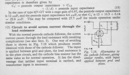
Someone recently forced me to look through part of RDH4. In the section on pentode cathode followers Langford-Smith was showing different ways to keep the screen grid current out of the cathode load. One of his suggested solutions was to put the load in the plate circuit, but apply the input signal between grid and plate. The result is a true anode follower. Of course it's mostly academic as it's pretty difficult to apply the input that way. A transformer might seem ideal, but you would run into some serious capacitance problems.
I suppose it goes without saying that you don't need to use a pentode ...
I suppose it goes without saying that you don't need to use a pentode ...
Attachments
I have noticed that the cathode follower and anode follower have different kind of nonlinearities. While the anode follower uses the direct version of the transfer characteristic, the cathode follower uses the inverse.
Does this explain subjective differences?
I actually feel that the anode follower sounds better. Is this a consistent experience?
Does this explain subjective differences?
I actually feel that the anode follower sounds better. Is this a consistent experience?
I like Nelson's Aleph as an emitter coupled base follower.
Of course, tube heads will want the enhancement mode
MOSFET replaced by a screen driven Pentode.
If Aleph's base follows a resistive divider from the Cathode.
The cathode of that Pentode can have a useful voltage gain.
Its definately on the sandy side of hybrids. Pentode mostly
for dissipation. With NPN in the error correction control seat,
driving the screen, and sandifying all the flavoring decisions.
Also tried simming Aleph with a Triode in place of the NPN,
as a cathode coupled grid follower. I didn't find that config
working as good as a plain jane Pentode cathode follower
for unity gain. And Cathode input impedance sucks. But for
gains over unity, it might still find use somewhere someday.
re: Ken
A diffl. pair driving a cath. (or emitter/source) follower with feedback to one of the pair's inputs is a standard buffer in any textbook.
For your diagram above, I would use a pentode for U1 and drive the output tube's g1. The feedback resistive divider could then be from the output's cathode to the U1 pentode's g2. Input is then on U1's g1, so high Z. Since the g2 and plate voltage of U1 track proportionally, the current intercept ratio of g2 will stay constant (ie, g2 looks resistive).
---------------------------------------
Since the posted request was for an ANODE follower, I would suggest just making the output a standard grounded cathode pentode with a resistive feedback divider from it's plate to a diffl pair 2nd grid1 (or could try the g2 for the feedback if the diffl pair are pentodes). (the output pentode grid 1 <or 2> drive comes off the diffl pair's 1st anode. Input is on the diffl. pair 1st grid1.) All tube that way. High input Z. (just another standard textbook buffer actually)
Don
Its a sand thing, you wouldn't understand...
(I'm kidding of course) Aleph has >=22K
looking into the emitter. The base (and to
some extent the collector) follow. I've been
abusing to excellent results. No so here.
As I drew it, backwards looking Aleph didn't
sim so hot in pure glass. Without the emitter
drop for an ultra predictable depletion mode
voltage reference. It just ain't the same...
Just cause I can, don't mean I should.
But I'm far too stupid to stop now.
------------------------------------------
Anyways, I redrew a better circuit.
Both more relevant, and better working.
Its no longer anything to do with Aleph.
Attachments
yagas said:Anyone tried something like this ?
I plan to build it for a friend of mine who insists on having the gain adjustable.
How the anode follower compares to cathode follower in terms of sound ?
Other than low input capacitance any other comments please ?
Mic
Tried it with several tubes. The cathode resistor needs to be bypassed or replaced by a low dynamic resistance device, such as a LED, shunt regulator, battery etc...
In your configuration it signifficantly increases the output impedance, (and if a standard resistor was used in the cathode, it would also lower open loop gain), which is not desirable in a 'follwer' that trades open loop gain for lowered output impedance - even if it is another form of feedback an linearises the tube before the plate to grid feedback is applied.
It can be shown that using a standard anode resistor instead of the CCS reduces open loop gain by about the same amount as it lowers open loop output impedance, so at first the use of a CCS seems moot. However, a CCS has the advantage of giving a lot more flexibility regarding the choice of operating point, and reducing the neccessary power supply voltage for a given output swing. That being said, with a CCS sonics will be more load dependant, the more the higher the tube's Ra. So, to get best performance, it would be a good idea to chose a tube with low Ra, which for sensible gains also tends to imply high gm is desirable.
Wavebourn said:It is not an anode follower, it is an inverting amplifier with gain=3 and input impedance = 100K
What? An anode follower isn't allowed to invert?
Or are you saying one isn't allowed to have gain?
What exactly must one do to be a follower of the
One True Anode???, or Shatner or whatever...
Anode follower driver fixup:
http://www.diyaudio.com/forums/showthread.php?postid=1775419#post1775419
http://www.diyaudio.com/forums/showthread.php?postid=1775419#post1775419
kenpeter said:
What? An anode follower isn't allowed to invert?
Or are you saying one isn't allowed to have gain?
What exactly must one do to be a follower of the
One True Anode???, or Shatner or whatever...
I can understand a current follower, when output current is equal to input current independently on output load resistance, or a voltage follower when output voltage repeats input voltage independently of a load resistance, but when something follows by nothing how can it be called "a follower"?
There are such terms as "inverter" and "amplifier", both apply to the thingy you discuss, but strictly speaking it is an inverting amplifier with parallel feedback by voltage.
However, you can conduct your research to find who was the first author of such a jargon term as an "anode follower", but it is far from strict academic terms.
Also, I heard the term "A follower with gain" that is also a jargon one.
In the OP's circuit there is a 1M grid leak (ground reference) resistor. In all of the articles I have looked at this resistor is not included in the drawings. Is it just assumed? It would seem to be necessary in order to prevent melt-down. Any preference for placing a grid leak at the grid v.s. at the signal input?
It is not often I disagree with Wavebourn, but the circuit shown is a modified form of anode follower. The modification is the added cathode follower. I think "anode follower" (or "plate follower") is a daft name, which may be the root of the problem, but that indeed is what it is called. I guess it gots its name from the fact that it can have a low output impedance like a CF, but the output is taken from the anode. Essentially, it is just the inverting opamp configuration but using a valve instead of sand.
- Status
- This old topic is closed. If you want to reopen this topic, contact a moderator using the "Report Post" button.
- Home
- Amplifiers
- Tubes / Valves
- Anode Follower