Hello John,
I am just back from Holidays in Thailand and I see your question... The best solution if you want to use the amplifier as an integrated amplifier instead of just a power amplifier is to replace the two on board trimmers by a stereo dual pot connected by wire to the trimmer pads, 20k to 50k log will be perfect")
As already told, you can also add a selector to chose different inputs...
If you are looking for more features like remote controlled preampli with motorized volume pot, relay input selector, power on/standby relay, I am currently designing a tube preampli for the EL34 Baby Huey (or any power amplifier in fact...), it will also work with my RIAA preampli Merlin RIAA Preamp
Marc
I am just back from Holidays in Thailand and I see your question... The best solution if you want to use the amplifier as an integrated amplifier instead of just a power amplifier is to replace the two on board trimmers by a stereo dual pot connected by wire to the trimmer pads, 20k to 50k log will be perfect
As already told, you can also add a selector to chose different inputs...
If you are looking for more features like remote controlled preampli with motorized volume pot, relay input selector, power on/standby relay, I am currently designing a tube preampli for the EL34 Baby Huey (or any power amplifier in fact...), it will also work with my RIAA preampli Merlin RIAA Preamp
Marc
Bonjour Seb,
Yes, you can use these Lundahl 9k transformer, but the impedance will not be optimal, these transformers are more convenient with 6V6 output tubes but for a lower power amplifier ! By the way what is the power of your Lundahl ?
With 6550 tube (that I like a lot ) I would use 4k transformer and 50 W minimum like Toroidy TTG-KT88PP TTG-KT88PP TOROIDY - Transformateur: de haut-parleur | TME - Composants electroniques or the more expensive Hammond 1650N that I had in stock and have used in my amplifier (both already suggested in this thread)...
Cordialement,
Marc
Yes, you can use these Lundahl 9k transformer, but the impedance will not be optimal, these transformers are more convenient with 6V6 output tubes but for a lower power amplifier ! By the way what is the power of your Lundahl ?
With 6550 tube (that I like a lot
) I would use 4k transformer and 50 W minimum like Toroidy TTG-KT88PP TTG-KT88PP TOROIDY - Transformateur: de haut-parleur | TME - Composants electroniques or the more expensive Hammond 1650N that I had in stock and have used in my amplifier (both already suggested in this thread)...Cordialement,
Marc
Bonjour Marc !
You're right. And to use my 9k (150W) transformer, it would be better to have highest voltage.
I am trying to design a SMPS because I'm working in electronic but no one in my company know how to calculate a resonant transformer :-(
Bonne journée,
Séb
You're right. And to use my 9k (150W) transformer, it would be better to have highest voltage.
I am trying to design a SMPS because I'm working in electronic but no one in my company know how to calculate a resonant transformer :-(
Bonne journée,
Séb
Last edited:
Thanks to Bandol I have a couple of PCBs in hand, and finally getting around to placing a Mouser order.
Couple of questions here as I scan over the BOM and start to order things.
I've noticed many different tubes suggested... is there any kind of agreement on which might be the superior / best all around choice? In other words, what besides having spare parts around would it make sense to go for 6V6, 6L6 or 6550? Figure it best to settle on that one before I splurge on output txs.
Re: C6, C7: I take it you chose the LGL 400V Caps for ease of casework? 25mm height is hard to beat. Which would be the parameters I should be looking at in this location? Ripple Current? I always like to go for longer life electros if possible... 2k hour rating doesn't instill much faith for me... sometimes these days I sneeze and ~2k hours have gone by...
I usually use the E91 Long-Life United Chemicons but I think a bit too big of a diameter for this PCB.
I might just use big screw type caps and tie them down inside the case.... or, I have some gigantic 60uf 600V Poly Film caps I might find a way to tie down inside the chassis. Do you think I could get away with some smaller values in those spots?
On C10, 11: You state the UFW is a tight squeeze. 12.5mm vs 10mm for the chemicon. Do you need all 100V? There seems to be 330uf in 10mm up to 80V in the chemicons.
R22: the BOM Panasonic Log says 50k log but code on BOM brings me to a 20k. I found a 50k log pot in the same series, but it says with bushing while item from bom specifies no bushing. Any material difference?
1uF, 100V: You chose an Epcos B3, 5mm width. I think I might try a Kemet F461 PP Film, 10mm width. Same length and lead spacing, but concerned about brushing up on nearby R's. Any idea if it will fit?
Power TX (115v): Looking at the Hammond 261G6, 45VA, 250V C.T. @ 130 ma, 6.3V @ 2A
Anyone realize benefits having separate B+ and filament Txs ? Has anyone built with DC Filaments?
Any other US transformer options would be appreciated.
Output: Hammond 1650N
Tube Sockets: Have always had good experiences with the Belton sockets despite not being very fancy looking. What is everyone elses favorite pc mount socket? Currently looking at these after having a chat about ceramic / heat.
Once I sort out the kinks I'll post my BOM and notes for easier ordering for others.
attached is BOM in progress.
Last edited:
It would have been nice if the GB PCBs provided a through hole space for the Belton grounded pcb mount sockets for the 12ax7A. Makes life much easier if you aren’t chassis mounting the sockets.The 12AX7A should go into a socket with a shield. I wouldn't use ceramic, the normal sockets do just fine. If you can shock mount them the amp will be less subject to shock noise as you operate switches.
-Chris
I’ve noticed the audio note preamp kits make good use of these throughout as well.
9-Pin Vacuum Tube Socket Belton Micalex PC Mount Shielded Base
Without it you have to run a wire and those cans for some reason don’t take solder well... also doesn’t look as clean.
If the shield isn’t grounded it won’t do you much good in rejecting interference... it’s something I see a lot of people curiously overlook.
Hi all,
So firstly, Marc thank you for your diligence and effort putting the pcb GB's together.
As one who popped in towards the end of the Group Buy, I haven't really been closely following this thread. However, now that I've begun the build I understand some of the sentiments expressed a few pages back by adam and scd.
I don't think this is a "take your different boards and go home!" kind of thing, or a territorial issue, but more so an effort to keep communication clear and helpful amongst builders. A main issue confusing communication (but also a big plus in other areas of course!) is the versatility inherent in the design.
For example, I've noticed many of the answers that are being asked crop up again and again, with builders (I think reasonably so) not wanting to read 195 pages of content to find the information they might require. Group Buyers purchasing PCBs are likely novices in amp building or would have opted to simply build point to point, thus they will likely need a bit more hand holding and be more easily confused. Also, we are dealing with High Voltage! This is an area where you want maximum clarity for personal safety!
While the parts list was in the group buy section, many other useful documents were sprinkled throughout the thread here. It might be useful to many to put them in the OP of the GB thread. Also, instead of "Baby Huey" or "Baby Huey Group Buys" perhaps you could label each variant to give more clarity in search results. Those who grabbed your PCBs are thinking more linearly- completion of a build, parts acquisition and assembly, et. al. It seems this thread would be of more productive use to expand on the great conceptual offering gingertube gave us, rather than litter it with questions that are more directed towards your pcbs.
So, please don't take as criticism. I very much appreciate your efforts and you are welcome to do as you wish of course. Likewise, I'm going to attempt to consolidate the information pertinent to these builds. Hopefully some of this will lighten your load and that of others!
For those who are interested in some build information for the most recent set of Group Buy PCBs I've started a new thread that i'll document my own findings that I dig out of these ~200 pages:
Baby Huey GB PCB - EL34 Build Thread
Obviously it's still a work in progress. Hopefully others will benefit and contribute- if you have any materials that would be useful to me please reach out by PM. I'd like to compile the BOM differences, Power Tx voltage and current, Output Tx values in relationship to one's tube choices and desired wattage in an easy referenced table.
I'll end with a philosophical question:
In ancient Greece, there was a legendary king named Theseus who supposedly founded the city of Athens. Since he fought many naval battles, the people of Athens dedicated a memorial in his honor by preserving his ship in the port. This “ship of Theseus” stayed there for hundreds of years. As time went on, some of the wooden planks of Theseus’ ship started rotting away. To keep the ship nice and complete, the rotting planks were replaced with new planks and this went on until all were replaced.
At this moment if you were to get on this ship, would you be on the ship of Theseus or a new ship? If you believe it to be a new ship, then at what point did it cease being Theseus' ship and become the new ship? Only after the very last plank was laid? Sometime before that? Does it matter the speed at which the planks were replaced? If they were replaced all at once? Very gradually in measured increments? What if the ship had not stayed in once place, but had been sailing from one place to another as each plank was replaced and thrown overboard?
And lastly, who cares who this Theseus guy is anyway? I just need a ship to get across the river.
Last edited:
Hi John,
Several answers to your questions:
1) the choice of the output tube is dependent of your target and of the output transformer, ie: 6V6 require a 8k OT and will give you about 15W, 6L6 is better with a 6.6k OT for 20-25 W max and 6550 can supply 50 W with a 4k OT
2) C6, C7: bigger capacitors can be used with a wire connection of course, but a better solution is to use a filtered DC power supply with a rectifier bridge and large capacitors to feed the Baby Huey PCB with DC current (you can replace the D1 and D3 diodes with jumpers and remove D2 and D4, but be careful to connect the + and - on the right input), it is still good practice to keep the small capacitors near the tubes...
3) C10, C11: of course you can use 80 V capacitors, but only if your bias power voltage does not exceed 50 V AC !
4) R22: 20k or 50k are both OK for the pot, but it must be log ! Nota: you can also use a dual pot fixed on the front panel and connected by wire if you want to make an integrated amplifier, you can even add an input sélector
5) C12: if you solder the capacitor under the PCB and the resistor on top there should be no problem...
6) Power TX: this transformer will not be powerful enough You will need at least 250 mA for high voltage and 7 A heater current for an EL34 version !!!
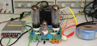
7) I have used DC filament with a 10 A 6.3 V switching power supply and was happy with it (see photo)
8) Hammond 370 HX should be a better solution even if 6.3 V is limit at 6 A for EL34 ? TOROIDY TSTA 250/001 is by far a much better solution with 16 A available for 6.3 V, two high voltage output 275 & 330 V AC and a separate 50 V supply for the bias
9) you don't need a shielded socket for the ECC83, it is a power amp diff amplifier and the voltage level at 2 V is high enough to have no noise, it is not like a RIAA amplifier at few mV...
Last but not the least, as I have already wrote several times, I prefer to discuss the EL34 Baby Huey on this original tread because what is important in this amplifier is the shunt feedback concept not the output tubes ! The Baby Huey has been built with many different output tubes : it started from a ECL86 design, became a EL84 design before to move to the EL34 version, the first version was made by Yves M. and after Ian (gingertube) made both EL84 and EL34. My contribution was to design 3 PCB for the 3 versions, the EL34 was the ultimate one which enjoy a successful interest on this forum. Therefor I will continue to answer the question on this forum only.
Cheers,
Marc
Several answers to your questions:
1) the choice of the output tube is dependent of your target and of the output transformer, ie: 6V6 require a 8k OT and will give you about 15W, 6L6 is better with a 6.6k OT for 20-25 W max and 6550 can supply 50 W with a 4k OT
2) C6, C7: bigger capacitors can be used with a wire connection of course, but a better solution is to use a filtered DC power supply with a rectifier bridge and large capacitors to feed the Baby Huey PCB with DC current (you can replace the D1 and D3 diodes with jumpers and remove D2 and D4, but be careful to connect the + and - on the right input
), it is still good practice to keep the small capacitors near the tubes...3) C10, C11: of course you can use 80 V capacitors, but only if your bias power voltage does not exceed 50 V AC !
4) R22: 20k or 50k are both OK for the pot, but it must be log ! Nota: you can also use a dual pot fixed on the front panel and connected by wire if you want to make an integrated amplifier, you can even add an input sélector
5) C12: if you solder the capacitor under the PCB and the resistor on top there should be no problem...
6) Power TX: this transformer will not be powerful enough
You will need at least 250 mA for high voltage and 7 A heater current for an EL34 version !!!7) I have used DC filament with a 10 A 6.3 V switching power supply and was happy with it (see photo)
8) Hammond 370 HX should be a better solution even if 6.3 V is limit at 6 A for EL34 ? TOROIDY TSTA 250/001 is by far a much better solution with 16 A available for 6.3 V, two high voltage output 275 & 330 V AC and a separate 50 V supply for the bias
9) you don't need a shielded socket for the ECC83, it is a power amp diff amplifier and the voltage level at 2 V is high enough to have no noise, it is not like a RIAA amplifier at few mV...
Last but not the least, as I have already wrote several times, I prefer to discuss the EL34 Baby Huey on this original tread because what is important in this amplifier is the shunt feedback concept not the output tubes ! The Baby Huey has been built with many different output tubes : it started from a ECL86 design, became a EL84 design before to move to the EL34 version, the first version was made by Yves M. and after Ian (gingertube) made both EL84 and EL34. My contribution was to design 3 PCB for the 3 versions, the EL34 was the ultimate one which enjoy a successful interest on this forum. Therefor I will continue to answer the question on this forum only.
Cheers,
Marc
Attachments
Thanks Marc,
Couple of more questions which I think will clear up a lot of confusion for me. Could you please explain / provide:
1. the BOM alterations required for the different tubes / tube families? I.e. 6V6, 6L6, 6550, KT88
2. The changes in the biasing / adjustment procedures for each.
3. The current and voltage differences for each.
4. The power transformer ratings which can accommodate the full range of tube options you suggest as possibilities in the GB.
It’s my understanding that total output power of the amplifier is also linked to its optimal plate voltage. Therefor it would seem that each tube choice would have a different optimal HV rating.
Am I right to assume the TOROIDY TSTA 250/001 will accommodate the voltage and current requirements of all the tube families you suggest as options?
Can you suggest a similar option that can be sourced in North America?
5. The output transformer wattage to provide a safe margin for all tube options within a given range. My basic understanding is that a larger wattage rating would minimize saturation issues? Is there a general rule of thumb for safe margins?
6. Kindly point me to a link of any simulation or test results of this circuit for the EL34 or any variants discussed on the pcb if they exist.
I’m curious to see if there are performance differences based upon tube type.
Did you measure THD on your 6AC7?
7. It appears that a given maximum wattage rating for output is an upper limit at which point the largest distortion figures will be present. I.e. for a speaker which might require 10-15W it might be more sensible to use a 25W design such as the 6L6 and ‘dial it back’ to minimize distortion. Can you explain some general rules of thumb in this regard?
Thanks for your time.
It’s still quite unclear to me what I should source to maximize performance parameters and minimize component waste.
Couple more that dawned on me after I posted that:
8. What kind of performance gains should be expected from using a completely dual mono configuration with separate power transformers? My understanding is that this will provide improved channel separation? Anything else I’m not aware of?
9. Would you recommend the use of a choke? What performance gains might be expected? I’ve noticed some others entertain this. What value and at what location?
Hi John,
8.) absolutely none unless the design or implementation is flawed.
9.) nope. Use a voltage regulator for small signal stages if hum or noise is a problem.
With tube electronics, most signal stages draw pretty constant current at all points. The power output stages draw peaks of current varying as the signal to the speakers does. A choke used to be less expensive than an electronic regulator, but that is no longer the case today. The regulator should have much higher performance levels.
-Chris
The Toroidy you mentioned above does not have a center tap. It’s H.V. is rated at 400mA AC. If you use the regular full bridge with cap input like on the BH pcb, your maximum available DC current will be 0.62 x 400mA so about 250mA DC (not 400mA DC). Pls consider this when choosing your PT.
A choke input bridge would be great but your B+ would be too low.
BR
Eric
A choke input bridge would be great but your B+ would be too low.
BR
Eric
Attachments
Last edited:
I've built both dual monoblocks and stereo with single power supply.
I can't tell the difference.
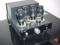
What I'm using at the moment, 6V6G and 6SL7, single power supply, Hammond 1608 Output Trannies and this power tranny:
86PP power transfomrer
Chassis was from Mable too.
Cheers,
Ian
I can't tell the difference.
What I'm using at the moment, 6V6G and 6SL7, single power supply, Hammond 1608 Output Trannies and this power tranny:
86PP power transfomrer
Chassis was from Mable too.
Cheers,
Ian
Attachments
Last edited:
Choose your favorite output tube and we can then advise more.
For around 30W then any off the octal base EL34, 6CA7, KT77, KT66, 5881, 6L6, 7581 will do your 30'ish watts while operating conservatively.
Of these EL34, KT77 were designed with Ultralinear Operation in mind but any of them can operate in UL mode.
My choice would be KT77 but that is personal opinion only and worth what most personal opinion is.
For guidance the higher gm tubes suit the BH design best (the first 3 listed above).
BUT
The BH amp I'm using at home now (pic posted above) uses 6V6G which have a gm of 1/3 of what KT77, EL34 give. The 6V6Gs also ONLY give 10 Watts out.
If you want the smaller 9 pin base then 7868 will better (power out wise) the EL84 at about 24 watts.
This is a tube from the later American "JukeBox" days. I've some on the shelf but haven't got around to trying them yet.
Cheers,
Ian
NOS 6AC7 or the new Tung Sol 7581A was what I was considering. I take it the 6AC7 aren’t designed for ultra linear mode as is the EL34? I’m a bit confused by the 6AC7 and what the relevant differences might be in application vs el34.
I also considered Russian variants like 6p3s-e
Basically, I didn’t want to pay crazy money for winged-c’s or NOS stuff coveted by guitar players and also that my experience with new production Chinese and Russian tubes has been less than stellar.
I don’t have enough tube experience to make a qualified answer as to a definitive favorite.
My favorite tube amp ever used GE 6550s and have really enjoyed an amp with KT88’s but my system has changed quite a bit then and I imagine some of the differences are circuit dependent.
Presently I’m using 87db efficient monitors and a solid state amp, so I don’t have a frame of reference in this scenario in particular.
I was planning to build with Bandol’s EL34 octal boards and would prefer to mount on the pcb without adapters due to my planned chassis.
Last edited:
Thanks Ian for your response.
I’m gradually wading through the entire thread and things are becoming clearer.
Additionally i read this from you on the amp above:
“As a practical exercise I have built a 6SL7 plus fixed biased 6V6G experimental version but low 6V6G Rg1 requirement (imposed by the fixed bias), lower 6V6 gm, higher currents for the 6SL7 etc. have meant that it just isn't in the same league - I keep running into limiting conditions everywhere as parametrers are pushed outside of acceptable limits - that is what I meant about SERENDIPITY with the 12AX7/EL84 version, in that case everything just ended up suiting everything else. This one is destined to have the shunt feedback deleted and cathode feedback from OT secondaries substituted instead. Even then I'm probably going to have to add MOSFET source followers to buffer the diffamp outputs into the 6V6s. It LOOKS stunning, just doesn't have sound to match - YET. Even so I don't believe it will ever match the ECC803S, EL84 version.”
Do you still feel the same way about other tubes in this design?
Also, for increased power why not for example a quad of el84s per channel rather than other tubes entirely? Wouldn’t this meet the 30wpc spec as well?
It starts to seem like what I’m attempting to build presently is a limited and less elegant realization of your original design in favor of a few watts that could be achieved with more el84s?
If my understanding is flawed please illuminate
Last edited:
- Home
- Amplifiers
- Tubes / Valves
- EL84 Amp - Baby Huey