I would like to avoid SS parts in the signal path, instead of using the mosfet follower in the push pull parallel 6V6 construction, is it possble to use a grid choke on the 6V6 output tubes grids, to lower the load on the input tubes?
How to chose between fixed and cathode bias? isn´t it best to use the solution with the 10 ohm resistors in the cathode, I guess that is called cathode bias? that will give a low impedance drive of the fransformer or am I way off hear?")
How to chose between fixed and cathode bias? isn´t it best to use the solution with the 10 ohm resistors in the cathode, I guess that is called cathode bias? that will give a low impedance drive of the fransformer or am I way off hear?
Hylle,
You can always wire up a tube cathode follower to replace the MOSFET, Ian did mention this in this thread.
Grid choke? You can always do that too, as long as you use the right choke to handle the grid current properly without making a havoc on the bias voltage.
Baby Huey is not you everyday design, its well worth your time to dig through this thread. You will be amaze by the wealth of information in it.
the solution with the 10 ohm resistors in the cathode, I guess that is called cathode bias?
The 10 ohm resistors in the cathode are for fixed bias; they allow a convenient measuring point to check the idle current by measuring the voltage drop across the resistor. They can be 1 ohm resistors or any other low value so that the cathode voltage is very close to ground. If you are using 10 ohm, 1 ohm, etc. the math is easy to determine idle current using ohm's law. Cathode bias will use higher R values, to raise the voltage of the cathode above the grid.
Last edited:
I would like to avoid SS parts in the signal path,
Why would you specifically want to do that?
Also, consider that the mosfet source followers are an integral part of the design of the Baby Huey, for reasons stated earlier.
Why would you specifically want to do that?
Possibly design aesthetic, but more likely superstition and foo...
Possibly design aesthetic, but more likely superstition and foo...
There are many who judge audio quality by equipment weight
I like the simple solution to avoid the Mosfets, I feel two gain stages is very elegant! But of cause if the simple solution is too simple, it is no good.
What do you feel about my suggestion of ease the load on the first stage by using a grid choke insted of a grid resistor? will that give enough drive for two x two push pull 6V6 tubes, and then leave out the mosfets ?
What do you feel about my suggestion of ease the load on the first stage by using a grid choke insted of a grid resistor? will that give enough drive for two x two push pull 6V6 tubes, and then leave out the mosfets ?
Last edited:
The advantage of the grid choke is that they have lo resistive value and thus void the bias voltage to swing when output tubes are pushed into grid current region (providing the bias voltage source has a lo impedance too).
The dificulty is that they must be of huge values (>> 100Hy) for they do not overload the driver at lo frequencies.
Unless you design a lo impedance driver and . . . the snake eats its tail !
Yves.
The dificulty is that they must be of huge values (>> 100Hy) for they do not overload the driver at lo frequencies.
Unless you design a lo impedance driver and . . . the snake eats its tail !
Yves.
Thanks for your comments Yves. Since I am a Newbi to tube designs, will you explain in details to my why the front circuit can not drive the 6V6 tubes, I know they have less gain as EL84 and I thougt if a grid choke is big enough it will be in Mohm range i most of the frequence range and ease the load on the input circuit, and it would keep the gain as high as possible.
Sorry for asking the same question several times. I just need to learn how a tube circuit loads the circuit infront. It is hard for me to understand since the input of tube-grid is so high an impedance in it self.
Sorry for asking the same question several times. I just need to learn how a tube circuit loads the circuit infront. It is hard for me to understand since the input of tube-grid is so high an impedance in it self.
I have finally started construction of my Baby Huey. It's the fixed bias version using James transformers and CLCLC power supply with all polyprop. caps.
A couple of quick questions: my working schematic has a shunt feedback resistor combo of 10k/18k/10k. I note on the schematic below the combo is 47k/18k/47k. Is this the optimum set-up?
And with the cathode resistors - they come together to another 10R resistor which then connects to ground. What is the function of this final resistor?
Thanks,
Rod
P.S. I just realised my schematic was the version with the shunt f/b from the UL tap. Just as well I checked it!
![IMGDEAD]](/community/proxy.php?image=http%3A%2F%2F%5BIMGDEAD%5Dhttps%3A%2F%2Fi282.photobucket.com%2Falbums%2Fkk257%2Froho_album%2FDSCF0947.jpg%5B%2FIMGDEAD%5D&hash=3443bbd4e882bdf4ac9feed05767d76c)
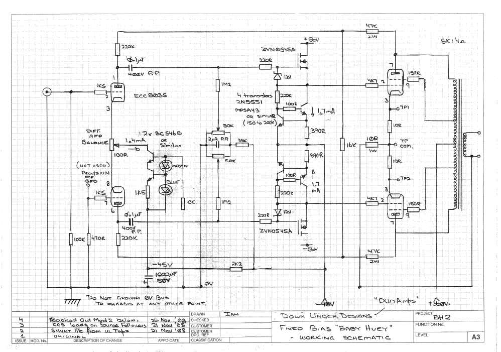
A couple of quick questions: my working schematic has a shunt feedback resistor combo of 10k/18k/10k. I note on the schematic below the combo is 47k/18k/47k. Is this the optimum set-up?
And with the cathode resistors - they come together to another 10R resistor which then connects to ground. What is the function of this final resistor?
Thanks,
Rod
P.S. I just realised my schematic was the version with the shunt f/b from the UL tap. Just as well I checked it!
Ian,
Thanks for the explanation. Now it make a lot of sense.
Hylle, you question is too general. Anything can drive anything, the question is what do you wish to achieve.
Since you mentioned your newbee status, I would suggest you build the circuit as it is & ask questions after the practical exercise. you may or may not like BH sound... & who know, you may actually convert to SS in the signal path.
Our local proverb says "If you have never tried, you will never know."
Audio_Idiot, you are right of cause. I will start to implement the circuit, with the mosfets when I have gathered the parts.
- I dont feel my question is too general, I guess the question insted could sound like, what will happen in this circuit if I leave out the mosfets?, and why is that happening?
- I dont feel my question is too general, I guess the question insted could sound like, what will happen in this circuit if I leave out the mosfets?, and why is that happening?
Being UL connected, the output stage will still has sizable miller's capacitance at the grid, paralleing multiple output tubes will multiply the miller's capacitace. The ECC83 has such puny current it may not get over the combine capacitance at the grid. This combine capacitance with the ra of the output tubes may lead to a high frequency roll off at audioble range. but you can still make sound with this, just not a lot of high frequency response.
A few general comments about the Source follower and "stuff" above.
1st - the BH scheme relies on trading output tube gm for reduced rp and hence reduced output impedance reflected to the secondary of the output tranny - that is why high gm tubes like the EL84 work better than 6V6, but I've buit several lovely 6V6 versions.
2) One way to get more gm is to parallel output tubes as Hylle is proposing. (The parallel output tubes can be considerd to be a single tube with double the gm).
3) You do need plenty of gain in the front end diff amp. With "normal" levels of shunt feedback, you will find that the amps sensitivity suffers if you use tubes with a mu of less than say 70, 6SL7, 12AT7 are OK but I would not want to use anything with lower mu. This is one reason why a cascode front end would probably work well, it give you a bit more gain to play with.
4)The source follower buffer offers a number of advantages:
- it allows use of fixed bias for the output tubes, without the buffer you need to keep Rg1 on the output tube grids high so as to not load the front end too much OR divide the shunnt feedback down too much. Without the buffer those Rg1 need to be 470K and that means cathode bias and either EL84 or EL34.
- If you current source load the source follower you have VERY high impedance which isolates any noise on the negative rail and it gives extremely tight control of the output tube grids and this helpd reduce noise contributed by the output tube grids. The 6V6/6SL7 version I'm running at the moment (with current source loaded source followers) has the blackest background (lowest noise) of any tube amp I've ever heard (that is any of about 20 DIY Amps and a similar number of commercail tube amps).
The bias is then applied to the source follower gate which is capacitively coupled back to the diff amp. The very high input impedance of the source follower allows the use of smaller coupling caps and so it is easier (and cheaper) to obtain better quality caps
Random afternoon ravings - hope there is something useful to BH builders.
Cheers,
Ian
Thank you for explaining, Audio_Idiot and Ian. I am learning more and more.
Ian, comments for your point 4) Since we need as high an RG1 as possible, why can a grid choke not be used instead of RG1? It has thousands of H and a low DC resistance of maybe 2 Kohm, and at the same time has Mohms load AC wise? If this choke is put in the fixed bias voltage lines to each grid, then even fixed bias should be usable on the first version without mosfets?
Am I totally of hear, Do you follow what i suggest? I just would like you oppinion Ian, I will not bother you more about this Grid choke idea if you "shoot it down" now !!
20to20 - Fair comment, all I can do is answer posters queries to the best of my knowledge/ability as they turn up.
Hylle,
I have no experience with grid chokes. The need to maintain high AC impedance down to the bottom of the audio range wories me. Those chokes would need to be 3 TO 4 THOUSAND Henries. I've tried to keep the basic design cheap so haven't investigated grid chokes.
Cheers,
Ian
Hylle,
I have no experience with grid chokes. The need to maintain high AC impedance down to the bottom of the audio range wories me. Those chokes would need to be 3 TO 4 THOUSAND Henries. I've tried to keep the basic design cheap so haven't investigated grid chokes.
Cheers,
Ian
- Home
- Amplifiers
- Tubes / Valves
- EL84 Amp - Baby Huey