Jaaps type of feedback must be better than "plate to plate" when dealing with triodes.
There are other "features" that are questionable, though. One of them is that you can not use a pot at input. Must be fed from a lowZ source! Best would be to feed differential through a transformer.
Also, as far as I know, the LND150 is a low voltage device and the whole circuit around it looks mystic...........
No trace of Baby Huey in it. Think Jaap was thinking of killing the Baby with this one ......
About LND150, my mistake(was thinking of the Lovoltech LU1014) ! Still I think its a waste of time&effort to insert the stuff here. The ECL82 triode has less than half Ri and almost double Gm of ECC83.
......About LND150, my mistake(was thinking of the Lovoltech LU1014)
! Still I think its a waste of time&effort to insert the stuff here. The ECL82 triode has less than half Ri and almost double Gm of ECC83.revintage said:Jaaps type of feedback must be better than "plate to plate" when dealing with triodes.
There are other "features" that are questionable, though. One of them is that you can not use a pot at input. Must be fed from a lowZ source! Best would be to feed differential through a transformer.
I will try with transformer in the future. I have now a 10K pot in use, but i draw a 100K because I thought it would be the right value.
jkeny said:I just wondered about it being called a baby huey without the plate to plate feedback with shunt - I thought that's what defined a BH.
LND150 is a high voltage part - up to 400V, I think
I suppose it is a family member of the BH.
Therefore I first posted here: http://www.diyaudio.com/forums/showthread.php?s=&postid=1766804#post1766804
More important: I have only 88 db speakers and my cd-player has low voltage-output. For that reason I connected a pre-amp a few moments ago. Pre-amp has 5842 tube and LL1630 transformer; 0A2/ccs PSU as here: http://www.ecp.cc/SSS.html . Must say that this BH cousin sounds very very good ! Thundering bass and nice highs (cymbals), and that with a small sized OPT and disastrous layout. Problem is I cannot compare to the original BH, it is possible (but unlikely
 ) BH sounds even better.
OT:
Jaap,
If you have a transformer preamp, why in the world do you do like this????
Ground the CT of your transformer secondary and feed from the first winding(+) into the 27k input and lift the second 27k from ground and feed the other winding(-) into this.
Probably you could also short(bypass) the caps from the pentode plates.
Still even a 10k pot it will be less than good as lowZ (600ohm) feeding is necessary.
revintage said:OT:
Jaap,
If you have a transformer preamp, why in the world do you do like this????
I am just testing for the best topology for a stand alone small amp (for my son). That IT coupled amp will certainly be made in some time.
By the way, the BH-cousin sounds so good that I cannot stop listening ( and jumping around ) while I have more important things to do. And I am listening only to 1 channel of the stereo signal. I can only wonder what great amp this can become with the el84 in stereo!

PLATE TO PLATE OR NOT
Not necessarily. Actually, that is feedback as we know it. Why would it be better?
If you calculate everything correctly and do a lot of sims, you will see that the plate to plate feedback (if I have not gotten everything wrong, that is the type of feedback I use in RH amps) gives better results, sonically at least (if the math is not important to you).
Correct me if I'm wrong.
Regards,
Alex
Jaaps type of feedback must be better than "plate to plate" when dealing with triodes.
Not necessarily. Actually, that is feedback as we know it. Why would it be better?
If you calculate everything correctly and do a lot of sims, you will see that the plate to plate feedback (if I have not gotten everything wrong, that is the type of feedback I use in RH amps) gives better results, sonically at least (if the math is not important to you).
Correct me if I'm wrong.
Regards,
Alex
Hi Alex,
When adopted to triodes the "plate-to plate" should give a lot worse results with higher THD. This due to a heavier load on the driver. Think this was explained in detail by our norwegian friend Svein earlier in this or Jaaps thread.
http://www.diyaudio.com/forums/showthread.php?postid=1729903#post1729903
But it is up to the listener to decide whats best IRL.
feedbacks
No, it does not. I have not read the cited explanation yet (will do), but if that was to be the truth, than the RH amps would work and sound very bad in triode mode.
Actually, the second generation expands to triode as well (300B) driven obviously by triode drivers... and should at least on paper work better than classic no feedback designs, or less classical designs with "overall feedback").
Further, the RH88 for KT88/6550 can be used in triode mode or pentode/beam tetrode mode, where the triode mode is penalized in power due to the efficiency of the pentode, but not in thd% or sound, for that matter.
To get back to the explanation, I have not read it, but I imagine that there is something wrong with it!
Regards,
Alex
Mixed plate to plate causes no problem as long as the output
tube is the Triode and the driver a Pentode. It causes a big
problem if mixed the other way round, and the driver is the
Triode.
Cause you got Mu and P2P fighting to "fix" two very different
things. And Mu (in this configuration) knows nothing of how
to linearize the Pentode, its influence becomes detrimental.
-----------------------------------------------
Having said the above... If you were to abuse the Cathode
of the Triode to drive the Pentode, and then plate to plate
feedback. Now that might just work.
Ummm..., I see problems with either scheme(s). Plate to plate feedback is really plate to grid of the output. If the output is a triode, then it could effectively lower it's Mu (if the drive is not looking lke a voltage source, but making distortion if the drive has varying Z). If the output is a pentode, then it will give it an effective Mu, so that will be more linear than a pentode running open loop (and lower output Z).
The problems crop up on the driver side for either setup. P to P feedback lowers the input impedance of the output tube, so it makes a triode driver distort unless it has a buffer. If the driver is a pentode, then the low Z load is OK to drive, but the driver is running pentode mode open loop (driver distortion still).
Putting the plate feedback back to the driver grid linearizes the whole bunch, but lowers the driver input Z there, transfering a loading problem back to the 1st stage or splitter. If the splitter is a Concertina with resistive loads, then no difference there I guess since the Concertina looks like a buffer anyway (as long as both loads are equal).
With a pentode driver, output plate feedbacks to it's screens could be helpful to linearize it without lowering the driver's input Z. And the g2 voltages track or are proportioned to the driver plate voltages then. So screen grid current distortion is minimized if the screen is idled at less V than the plate. (Looks like a resistive and linear load) One caveat here is that the transfer function of g2 is closer to 3/2 power and a high gm g1 is closer to 2 power due to "island effect". But this can be minimized by selection of operating point to stay out of the "island effect" territory at low current. I have gotten quite good results.
Another option is to use a triode or pentode driver with output plate feedbacks to the driver cathodes and a CCS as the triode driver load (or could for the pentode too, just makes for a huge loop gain). The low value feedback attenuator resistor at the cathode avoids increasing driver plate Z much (probably want a buffer for the pentode case anyway). This scheme increases the input signal required by the driver, but input Z remains high. Cathode feedback is very linear since it is relative to the grid.
Another issue to consider is that output plate feedback is relative to B+, not ground, as far as signal going thru the xfmr. But P-P cancels most of the problem.
My two cents.
Don
smoking-amp said:
The problems crop up on the driver side for either setup. P to P feedback lowers the input impedance of the output tube, so it makes a triode driver distort unless it has a buffer.
Don
In my tryout (see post 700), I use ecl82 with output in pentode mode and triode driver with LND150 ccs on top (but using the mu - output !) and a ccs under the cathode.
Does the mu-output count as a " buffer" and is this perhaps the reason it sounds so good ?
I have not had the time to try other driver outputs. I see three alternative options:
- take the driver output from the plate of the triode
- snap the 1K resistor between source LND150 and plate in two and take the output from the middle of the two resulting 500R resistors
- take the output from the cathode of the ecl82 triode and add another gain stage before it (fet or triode)
By the way, could the last option be called a SLCF ?
And of course I have not forgotten the suggestion of Revintage to bring back the inputtransformer.
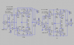
Did a quick sim with the two types of feedback. Made use of the possibilty to DC-couple of the feedback.
Anyway tested them as they are. The Huey version distorts and also clips earlier. Have not made a deeper analysis af feedback degree etc. Will adust to the same local NFB later.....
A big BUT though: The Huey is feedbacked over one stage, the X-coupled over two.........
Anyway tested them as they are. The Huey version distorts and also clips earlier. Have not made a deeper analysis af feedback degree etc. Will adust to the same local NFB later.....
A big BUT though: The Huey is feedbacked over one stage, the X-coupled over two.........
Attachments
FEEDBACK, POSTS, AND ARMCHAIRS
Well, yes, I read the link. I expected it to be something long and thedious to read and that I would not have the time or will to read it carefully. But it isn't. It is hardly an explanation. Just a statement.
The rest of the comments also seems like people from another planet - to me. No pun intended. But, if I were to listen to you and your explanations, I would have never designed any of the RH amps. Are you familiar with those? I believe you are. They work. They are for real. And, the key ingredient is what we might call plate to plate feedback.
There is a difference, though... but it is very superficial, if you have a deeper knowledge and understanding of things: RH amps are SE, what you are discussing are push pull amps. To me, there is not that much difference: take two RH amps (SE) and place them "one against the other" and you get an RH PP amp. What you need now is a phase splitter, and that element is one I am never comfortable with. But the phase splitter is just a stage, while the amp itself is the same principle, multiplied per two.
Finally:
Can you do a sim of one of the RH amps? Maybe your sims are not correct, maybe the models are off, maybe there are mistakes in the basics of the simulation? I use to "break" the simulation into components, i.e. the output transformer is actually a choke (primary inductance) in parallel with a resistor (primary resistance) and the DC resistance of the transformer's primary can be represented by a resistor placed betweem the choke and the PS in order to have a voltage drop... Just take a look at some of the previously published schematics, sims, and my site.
Well, there is always the chance that I am off in a hostile thread where others rule the way. If that is the case, I excuse myself and leave you in your world. Everyone has the right to choose his own schematics, but physics cannot be bent and where there is knowledge and results, you just have to admit them.
Regards,
Alex
This is as expected. The feedback anode-anode presents a much lower impedance load to othe driver tube resulting in a steeper load-line. This will limit possible feedback that can be applied before driver distortion becomes excessive.
Well, yes, I read the link. I expected it to be something long and thedious to read and that I would not have the time or will to read it carefully. But it isn't. It is hardly an explanation. Just a statement.
The rest of the comments also seems like people from another planet - to me. No pun intended. But, if I were to listen to you and your explanations, I would have never designed any of the RH amps. Are you familiar with those? I believe you are. They work. They are for real. And, the key ingredient is what we might call plate to plate feedback.
There is a difference, though... but it is very superficial, if you have a deeper knowledge and understanding of things: RH amps are SE, what you are discussing are push pull amps. To me, there is not that much difference: take two RH amps (SE) and place them "one against the other" and you get an RH PP amp. What you need now is a phase splitter, and that element is one I am never comfortable with. But the phase splitter is just a stage, while the amp itself is the same principle, multiplied per two.
Finally:
Anyway tested them as they are. The Huey version distorts and also clips earlier. Have not made a deeper analysis af feedback degree etc. Will adust to the same local NFB later.....
Can you do a sim of one of the RH amps? Maybe your sims are not correct, maybe the models are off, maybe there are mistakes in the basics of the simulation? I use to "break" the simulation into components, i.e. the output transformer is actually a choke (primary inductance) in parallel with a resistor (primary resistance) and the DC resistance of the transformer's primary can be represented by a resistor placed betweem the choke and the PS in order to have a voltage drop... Just take a look at some of the previously published schematics, sims, and my site.
Well, there is always the chance that I am off in a hostile thread where others rule the way. If that is the case, I excuse myself and leave you in your world. Everyone has the right to choose his own schematics, but physics cannot be bent and where there is knowledge and results, you just have to admit them.
Regards,
Alex
Hey Alex,
Never occured to you that your sims could be wrong ? Please show your sims if you don´t agree! If you use LTSpice we could exchange *.asc . Makes it easier to discuss then.
Maybe your sims are not correct, maybe the models are off, maybe there are mistakes in the basics of the simulation?
Never occured to you that your sims could be wrong
? Please show your sims if you don´t agree! If you use LTSpice we could exchange *.asc . Makes it easier to discuss then.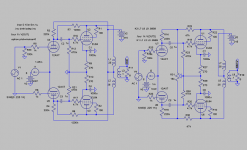
Plate to plate feedback for SE with a triode driver will lower the output Z (better damping) but cause more driver distortion unless buffered. For SE, this would just mean more 2nd Harmonic, which many like the sound of. Lower distortion does not necessarily translate to better sounding to some (or to many).
One would expect the higher loop gain of NFDBK around two stages to give lower distortion than just one stage (at least up until hard limiting). One caveat with the crossed feedbacks, back to the driver grids, is that when leaving class A operation of the outputs, the feedbacks to have to pass thru the xfmr. This can lead to instability problems. This is also an issue with the crossed feedbacks to the driver screens scheme. This problem can be avoided with an Elliptron-like CFB setup on the outputs, where each tube uses both sections of the CFB winding.
On Jaap's design in post 700, there is no feedback to the output grids (or P-P), so the driver buffering is really an option.
RE: post 719 The extra B+ driver load resistors are one way to fix the driver current problem of the B-H, but a better one would be some CCS's on the drivers (would require a common mode servo of the bottom CCS to set plate voltage stably)
- Home
- Amplifiers
- Tubes / Valves
- EL84 Amp - Baby Huey