 to keep you from getting zapped by B+ when powering down to work on the amp.
Ken (Audio_Idiot) asked if I could post working schematics of the fixed biased Baby Huey Monoblocks.
This is what the amps looked like as of last night - note that I have backed out the change of the shunt feedback from the Ultralinear Taps and shunt feedback is off the anodes again. I felt that the speaker impedance vs frequency curve had too much influence when shunt feedback was taken from the UL Taps and I was loosing too much bass (although I though the fine detail was a bit better) - I may have to try this again. The Source follower CCS loads are "Basic" and can be improved.
Cheers,
Ian
Attachments
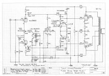
And now you see why I'm normally not keen to post working schematics - The feedback from the UL taps mod is back in. Last nights testing showed this is much better. Also pushed up the shunt feedback level for better bass control. It will stay this way for at least a few weeks and maybe forever. Updated Amp schematic attached.
Cheers,
Ian
Cheers,
Ian
Attachments
gingertube said:Ken (Audio_Idiot) asked if I could post working schematics of the fixed biased Baby Huey Monoblocks.
This is what the amps looked like as of last night - note that I have backed out the change of the shunt feedback from the Ultralinear Taps and shunt feedback is off the anodes again. I felt that the speaker impedance vs frequency curve had too much influence when shunt feedback was taken from the UL Taps and I was loosing too much bass (although I though the fine detail was a bit better) - I may have to try this again. The Source follower CCS loads are "Basic" and can be improved.
Cheers,
Ian
Ginger,
This may be another of my idiot-ish question...
I hope this make sense... From what I understand, this partial feedback is a form of Voltage Feedback,it is the voltage amplitude feed into the input that matter the most. a feed back signal taken from UL tap would be smaller (only a portion of the L) as it in essence a voltage divider of the full coil... I also observed that the shunt resistor for the plate is larger then the one from the UL tab. and the shunt resistor will attenuate this signal proportional to its size.
Now my real idiot question, is there any need to play with the UL tap?
Cheers
Ken
Hi,
My earlier post
the two articles cover lots of detail technical datas of CCS (at least to an idiot like me") )
)
The articles covers the use of LM317 and reference diode for high noise rejection.
I hope we can further discuss this if it is not off topic.
Cheers
Ken
My earlier post
Audio_idiot said:Hi,
I hope this is relevent
http://www.audioxpress.com/magsdirx/ax/addenda/media/jung2778.pdf
http://www.audioxpress.com/magsdirx/ax/addenda/media/jung2779.pdf
Cheers
the two articles cover lots of detail technical datas of CCS (at least to an idiot like me
)The articles covers the use of LM317 and reference diode for high noise rejection.
I hope we can further discuss this if it is not off topic.
Cheers
Ken
Ken I'm not sure what you are asking.
First note that the Feedback pickup from the Ultralinear Taps is back in again.
The Signal voltage at the UL Taps is 40% the signal voltage at the anodes so you don't need to divide the voltage down as much to get the level of feedback voltage you want (as you said).
In addition to that if we say that the output transformer load presented to the output tubes is nominally 8 KOhms anode to anode and that impedance is proportional to the SQUARE of the turns ratio then from Ultralinear Tap to Ultralinear Tap the impedance is 0.4 squared x 8K = 1K28.
When taking the feedback of the anodes I wanted a divider chain (47K + 16K +47K) which was at least 10 times the 8K load presented by the output transformer so that the output tubes are delivering the bulk of their power into the output transformer and not into the feedback divider chain.
When we take the feedback from the Ultarlinear taps the divider should be at least 10 times that 1K28 instead, so the resistors can be smaller and you don't loose as much DC Voltage due to the front end diff amp current flowing through them.
The Feedback from the UL Taps went back in during a marathon test and listen session last night and I posted the moded amp schematic when I got to work about 4 hour ago. It really does sound much better with respect to detail and in particular it has a lovely loping pace and rhythm compared to taking feedback from the anodes.
To get EXACTLY the same level of feedback as before, the divider off the UL Taps should be 10K + 9K1 + 10K. This is what I started with last night but then tried increasing the feedback level by changing that 9K1 cross connect to 10K, then 12K then 13K then 15K and finally to 18K which means I doubled the amount of feedback. This was mostly noticable in better bass control. That last step 15K to 18K did not make much difference and I may go back to 15K but this is just "fiddling at the edges".
The 2 papers you posted links to are probably amoungst the best papers on Current Sources - they are cerainly in my filing cabinet of useful info. They don't cover all the options but give you a good "toolkit".
Cheers,
Ian
Ginger,
You understood my question fully.
The UL tap shunt feed back make sense to me now.
I am still looking for excuses to delay my build
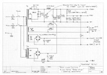
I also see that you derive the output tube bias voltage from the -48V rail for the source follower, how would you go about the current balance of the two output tubes? I meant any plans for autobalancing servo?
Cheers
Ken
You understood my question fully.
The UL tap shunt feed back make sense to me now.
I am still looking for excuses to delay my build
I also see that you derive the output tube bias voltage from the -48V rail for the source follower, how would you go about the current balance of the two output tubes? I meant any plans for autobalancing servo?
Cheers
Ken
Ken the "bias" is applied to the gates of the source followers via adjustment pots. Each Output Tube has a 10 Ohm resistor in its cathode, the voltage drop across that resistor tells me the idle current. With the input shorted (no signal) - on each side I measure the voltage drop across the 10 Ohm resistor and set the pot for that side to get the idle current I want. For example with the 360V rail I have right now I set for a reading of 0.32 Volts across the 10 Ohms which means 32mA idle current. That means I have about 11.5 Watts of dissipation in the tube. The idle currents are ONLY balanced cause I adjust them to be the same on each side.
A Bias Servo is possible but no plans at this time.
The original CCS biased Baby Huey does not have or need any adjustment and is automatically balanced by the action of the CCS in each output tube cathode (The idle current flows through the CCS). It is one of its "endearing features" but the trade off is that the CCS'es require bypass caps (ALL of the signal current runs through those capacitors) and the sound is influenced by those capacitors.
Best I get back to what I'm meant to be doing (writing a Laser Safety Paper)
Cheers,
Ian
adamus said:I have a couple of options for the bypass caps, either silmic 1000uf (i have 4 in the parts bucket) or i have 4 220uf blackgates.
i assume i would lack bass with the 22ouf blackgate?
Use both the 1000uf and the 220uf blackgates. Bypass them with a 1-2uf film cap also. Gingertubes original schematic shows two electros + a small film bypass (I think threy were 4700u+470u+1u PP). Later posts in this thread show folks using 1000U or so. My Hueys are presently running 1000u BG+100u BG+ .1 PP
Once you get the amp up and running, dial in the caps to suit your taste.
Hi,
Did some tinkering on maths and theory my own.
After studying the UL tab BH, It made me itch to put up something fast.... I only have a 185V power trans and some really cheap 0-3k5-5k SE OPT.
I calculated the %tage feedback of the latest BH circuit is
40% x 9k/19k= 18.9%
I recall that I have a pair of really cheap SE OPT with optional 3k5 & 5k tap, I did a quick measurement and know that they are on the the same coil. Then I calc the tap 3k5 on 5k as Sqrt(3k5/5k)=83.7%
so if I reverse the polarity of the SE primary coil, then we will have a 100-83.7%= 16.3% UL tab. near enough to Ginger's final test point.
I then recalled I have a power trans with 2 primary coil 0-185V & 0-6.3V, the 185V tap will give me ~250Vdc, should be enough for EL84...
If I use a 12AX7, set it at 0.5~0.6ma Ia with a CCS, I can feed the driver stage directly from the 16.3% tab!Use a large resistor to of 200K to bring it down to ~150V at the plate, and 0.5~0.6mA shouldn't cause much problem to the EL84 output stage as well...
BUT I start to puzzle over
1)what grid resistor should I use.
2) if I can drive the EL84's effectively with about 1/2 mA and very high Zo of the 12AX7 w/o a source follower??
This SE clearly looks like (at least to me) a kind of partial Voltage feedback rather then a I/V converter stage..
BTW, how would I know the Ro of the output stage? Is there any maths for this?
the 12AX6 give about 60V max onto the EL84 grid, looks like the EL84 will clip fairly early as well.
I'm new to these please point me the right direction.
Cheers
Ken
**ps, I'm even tempted to direct couple the two stages loftin-white style....
Ken,
Can't really comment on your proposed SE design.
Others,
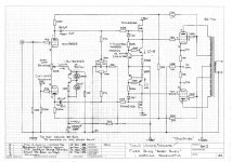
More work last night on the working schematic of the fixed bias BH at post #604.
I kept pushing up the shunt feedback via the cross connect resistor but just could'nt get the sound I wanted. I needed a bit more bass roundness and tube warmth. That suggested the feedback was already too high so I went back to the 10K + 9K1 + 10K arrangement from the UL Taps and then started REDUCING feedback instead. 8K2 in place of the 9K1 gave me a fair amount of the sound I was looking for. May even try 7K5 BUT 8K2 is really lovely.
Lesson here for young players - If it doesn't sound "right" and pushing up the feedback does'nt get the sound you want, then try reducing the feedback instead.
I also played around with the common resistor in the cathodes of the EL84s. This was to see if I could implement that 3rd harmonic distortion reduction scheme posted earlier (which from Sheldons tests back on page 19, Posts 451 and 452 was also an intermodulation distortion reduction scheme).
According to Sheldons observations of his results and Allen Wrights published PPC1A circuit a Common 39 Ohm resistor would be ideal.
I fitted a 39 Ohm and then just experimented by shunting it with a 10 Ohm ( bias in the tubes set with the 10 Ohm shunt in place and just accepting that the idle current dropped with the shunt removed). The 39 Ohms I believe DID sound better so that is what I'm running now (with bias adjusted). This was a purely listening test. No empirical testing.
Its now well passed the stage that you need to listen to any changes over a few days with many different music selections. Some stuff which now sounds bad is because the "recording" is bad and we are revealling its "warts".
A vinyl session is now in order.
Cheers,
Ian
Can't really comment on your proposed SE design.
Others,
More work last night on the working schematic of the fixed bias BH at post #604.
I kept pushing up the shunt feedback via the cross connect resistor but just could'nt get the sound I wanted. I needed a bit more bass roundness and tube warmth. That suggested the feedback was already too high so I went back to the 10K + 9K1 + 10K arrangement from the UL Taps and then started REDUCING feedback instead. 8K2 in place of the 9K1 gave me a fair amount of the sound I was looking for. May even try 7K5 BUT 8K2 is really lovely.
Lesson here for young players - If it doesn't sound "right" and pushing up the feedback does'nt get the sound you want, then try reducing the feedback instead.
I also played around with the common resistor in the cathodes of the EL84s. This was to see if I could implement that 3rd harmonic distortion reduction scheme posted earlier (which from Sheldons tests back on page 19, Posts 451 and 452 was also an intermodulation distortion reduction scheme).
According to Sheldons observations of his results and Allen Wrights published PPC1A circuit a Common 39 Ohm resistor would be ideal.
I fitted a 39 Ohm and then just experimented by shunting it with a 10 Ohm ( bias in the tubes set with the 10 Ohm shunt in place and just accepting that the idle current dropped with the shunt removed). The 39 Ohms I believe DID sound better so that is what I'm running now (with bias adjusted). This was a purely listening test. No empirical testing.
Its now well passed the stage that you need to listen to any changes over a few days with many different music selections. Some stuff which now sounds bad is because the "recording" is bad and we are revealling its "warts".
A vinyl session is now in order.
Cheers,
Ian
my baby huey is moving along...slowly...damn having so much work on.
An externally hosted image should be here but it was not working when we last tested it.
any advice on layout... just playing around at the moment.
The white sheet is the same size as my chassis. I will use shieldd wire for inputs so are too bothered about the length to the volume pot.
The white sheet is the same size as my chassis. I will use shieldd wire for inputs so are too bothered about the length to the volume pot.
An externally hosted image should be here but it was not working when we last tested it.
What I would do:
Put the two input RCA Sockets top left (insulated from chassis).
Run shielded cables down left side and around to volume pot.
Signal ground to chassis earth connection point near the volume pot
Power input rear right with chassis ground SAFETY connection in that corner.
Where ever possible use transformer mounting bolts and tube socket bolts to mount the boards to minimise the number of bolts through the top panel (aesthetics ONLY).
Looking good so far.
Cheers,
Ian
- Home
- Amplifiers
- Tubes / Valves
- EL84 Amp - Baby Huey