EL84 fixed bias
Ian,
Thanks so much for guilding me along and the amp is running happily now. It sings within an hour and my impression is this amp sounds more solid and punchy with lots of weight. I thought I better let it run for another weeks then to compare with the baby huey. Will report later.
You're exactly right that I put the leds the opposite side, and everything seems working ok after I switch them back.
Anode of 12AX7 127v, 126v
the top BC546 at point B -25.8v
the bottom BC546 point E -29.3v
between 1k8 & 2k2 -31.72
point after ZVN0545 -10.25
I've set the EL84 running at 37mA, and feed back at 22k
Thanks again
Albert
Attachments
Albert,
Glad to help and are happy to hear that its all running.
All the voltages you quote look good. Well - the 12AX7 anode voltages are a little lower than I normally would aim for.
If you want to try finessing this, you will need to drop the CCS current a little. That means adjusting that 1K8 resistor up in value a bit.
You could try 2 x 3K9 in parallel (1K95) or even a 2K2.
This MIGHT make a slight improvement in sound.
Cheers,
Ian
I'm hip deep in my first amp build, and I have a few ultra-newbie questions...
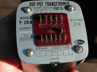
I'm somewhat confused as to the wiring for my O/P transformers.
Specifically, how do I figure out which terminal is the center tap for the primary side?
I would also like to confirm that the terminals marked S and G are the ultralinear taps that I should be using for the baby huey build. (I do not have any docs for the O/P transformers).
Attachments
Hi all,
I just finished to build the EL84 version of Baby Huey.
One channel is working, the other one needs some debugging.
The sound is very impressive as far as I can tell at this stage. So far I only built guitar amps and a K-502 kit, which I modified heavily, so not so much to compare to.
The Baby Huey sounds very detailed with an amazing bass.
I can not wait to have the other channel working (the CCS does not work correctly, I guess I did something nasty to one of the transistors).
I had to include some modifications to the power supply since my power transformer gave too high HT voltage. The power supply looks like this now: UF4007 diodes -> 4.7uF PP film cap -> 1.5H choke (with 0.22uF snubbers) -> 22uF electrolytic -> 100R ->330uF. From there I split up for the two channels as in the original schematic (47R -> 100uF electrolytic paralleled with 4.7uF film caps).
I was curious about the feedback and did some testing there.
The shunt feedback seemed a bit tricky because there is definitely some range of values where the effect of change is not so obvious. I ended up with 18k shunt feedback (I could not decide if it sounded better than 20k) and a variable global feedback. For global feedback I used the 12k (suggested in the original schematic) in series with a 50k stereo pot.
It is very nice to listen to the effect of feedback.
My wife and I both (independently) decided that it sounds better with less feedback. The amp sounds more lively. If you dial in the feedback it is as if someone would put a cloth in front of the speakers. Somehow muted, less "emotional". I have to think of increasing the pot value or omitting it (although I like the idea of variable feedback).
BTW the amp is amazingly quiet, no hum at all (even with my ear to the speaker). There is some very very weak noise (ssssh) when cranked up all the way and no input signal (the amp would blow out the windows with input signal). At normal listening levels there is nothing coming out of the speakers with no input signal.
Once the second channel is working I will post again -maybe with some pictures. This is my first built from scratch and if I compare to the quality of craftsmanship usually seen here on the forum I wonder if this is a good idea. Especially the interior is quite crowded and messy (after a few modifications here and there it looks quite similar to a bowl of pasta).
Thanks to gingertube for this incredible amp and his support on this forum.

Cheerio,
I just finished to build the EL84 version of Baby Huey.
One channel is working, the other one needs some debugging.
The sound is very impressive as far as I can tell at this stage. So far I only built guitar amps and a K-502 kit, which I modified heavily, so not so much to compare to.
The Baby Huey sounds very detailed with an amazing bass.
I can not wait to have the other channel working (the CCS does not work correctly, I guess I did something nasty to one of the transistors).
I had to include some modifications to the power supply since my power transformer gave too high HT voltage. The power supply looks like this now: UF4007 diodes -> 4.7uF PP film cap -> 1.5H choke (with 0.22uF snubbers) -> 22uF electrolytic -> 100R ->330uF. From there I split up for the two channels as in the original schematic (47R -> 100uF electrolytic paralleled with 4.7uF film caps).
I was curious about the feedback and did some testing there.
The shunt feedback seemed a bit tricky because there is definitely some range of values where the effect of change is not so obvious. I ended up with 18k shunt feedback (I could not decide if it sounded better than 20k) and a variable global feedback. For global feedback I used the 12k (suggested in the original schematic) in series with a 50k stereo pot.
It is very nice to listen to the effect of feedback.
My wife and I both (independently) decided that it sounds better with less feedback. The amp sounds more lively. If you dial in the feedback it is as if someone would put a cloth in front of the speakers. Somehow muted, less "emotional". I have to think of increasing the pot value or omitting it (although I like the idea of variable feedback).
BTW the amp is amazingly quiet, no hum at all (even with my ear to the speaker). There is some very very weak noise (ssssh) when cranked up all the way and no input signal (the amp would blow out the windows with input signal). At normal listening levels there is nothing coming out of the speakers with no input signal.
Once the second channel is working I will post again -maybe with some pictures. This is my first built from scratch and if I compare to the quality of craftsmanship usually seen here on the forum I wonder if this is a good idea. Especially the interior is quite crowded and messy (after a few modifications here and there it looks quite similar to a bowl of pasta).
Thanks to gingertube for this incredible amp and his support on this forum.
Cheerio,
Hi everyone,
I could not wait and had to finish the second channel last night.
Now it is much easier to tell the overall sound.
I really like what I hear, but somehow I have the feeling there is still something missing. The amp has a very good bass response, actually there is really a LOT of bass.
But in the high frequencies the amp sounds very correct, a bit emotionless.
There is definitely room to tweak.
My version of Baby Huey runs B+ at ~300V. The idle current of the EL84s is set to ~38mA. I realized that the CCSs for the diff. amp might need to be adjusted because I read ~110V on the anodes of the ECC803.
Seems like the idle current is a bit high there. What I learned from the previous posts this should be between 140-190 Volts.
This is my first "from scratch build" and I am quite a nooby, so please be patient with my questions.
As far as I understand this CCS arrangement, it is the LED forward voltage that is important, not so much the LED current. I am asking this because I picked just two standard 3mm red LEDs from the parts bin. Now I am wondering if this might have been low current versions which would end up with ~2mA instead of the typical ~20mA LED current. The voltage drop should be the same AFAIK.
I measured all resistors in the CCS which are fine (+/- 5% tolerance). Should I just increase the 1k resistor?
This might be just a technical improvement, since the amp is running quite fine at the moment. But I really want to get the most out of the circuit and I have the feeling that my version is not running at the optimum.
Thanks for any input/help.
Martin
If the sound is a "bit formal" sounding it could be due to the overall global feedback. The plate to plate feedback doesn't really have this failing.
Try substituting a suitable pot for the global feedback resistor and then varying it and seeing what you like.
The circuit shouldn't really need any global feedback, if the output transformers aren't totally crappy.
Shoog
Try substituting a suitable pot for the global feedback resistor and then varying it and seeing what you like.
The circuit shouldn't really need any global feedback, if the output transformers aren't totally crappy.
Shoog
Hi Bayermar,
I can confirm Shoogs' statement to drop the global feedback completely. The amp is stable without it, and sound will most probably improve.
Other elements that influenced the sound signature during my tests:
- Value of the cross-connect resistor (R between the two anodes of the
ECC803). I used 16k as per schematic, that's where life comes to the
amp. Higher values up to 47k make the amp sound more
transistorlike. The value also depends on the speakers you have.
16k was great for my fullrange horns.
Gingertube commented this resistor in post #418
- Bypass caps on the EL84 CCS. Swapping the electrolytics against
Blackgates made a big difference in sound to me (although i'm against boutique parts in general)
- The tubes themselves.
Russian military EL84M tubes had a very tight deep bass but were
a bit harsh in the mids & highs (-> read transistorlike)
Finally I ended up with old NOS-tubes (Philips ECC83 and Tungsram EL84).
Tube rolling was very beneficial with the Babyhuey, it's very
easy to spot the tubes you like best here. Unlike my earlier amp
(Eico HF86 topology) where changing a russian EL84M against a
Tungsram EL84 was inaudible. The Babyhuey sounds great
with every tube brand but has the potential to further improve with
a top tube.
Kind regards,
Yves
Fixed bias EL84
Ian,
My fixed bias has been running for almost 2 weeks and I did some comparison with the original baby huey last night. The solid fast and acurate lower end of the fixed bias is obviously better than the original. It's sound stage is deep and wide with a sparkling highs.
I'll wait a bit longer for the blackgate to break-in. Ah........ it might surprise me with a completly different picture. Will report later.
I'll keep the baby huey for my horns and the fixed bias is sitting on my main listening room with my lately finished speakers "PMS"
I can't wait to see your new design - the 300b. Please do let me know if there is anything coming up.
Albert
Hi Shoog and Yves,
Thank you for your fast reply.
The "formal" sound might indeed be due to the global feedback. I will try to leave the global feedback out altogether.
I will further test different values for the cross-connect resistor again, now in stereo this might give different results.
My output transformers are Hammond 1608 (keeping the budget low) and I use a matched quartet of JJ EL84 tubes.
I will see, what else I can find and try to roll them around a bit.
I will report back as soon as I can.
I figured from the descriptions in the previous posts that this amp should sound a bit more like a single-ended amp and the "coolness" of the mids/highs surprised me a bit.
Any comments on the low anode voltages of the ECC803?
I realize I should probably give more data here. I will measure the cathode and grid voltages and report back. This might make it easier to judge the situation.
Thanks again,
Martin
Guys - I missed a day, 8 hour trial flight of the new Laser Airborne Depth Sounder for the day job.
bayermar,
110V on the anodes is a little lower than I normally run. Increase the 1K emitter resistor in the CCS to 1K2 to decrease the CCS current a little. If you still have less than 140V then you could try a 1K3 (or 2 off 2k7 in parallel to give 1K35 if you don't have that less usual value).
Albert,
I think the fixed bias version with the source followers is, as you seem to think, always going to be better. There are a number of reasons for this:
1) elimination of cathode bias and direct coupling of the output tube grids will prevent any blocking distortion.
2) lower value Rg1 on the outout tubes ties them down tight and minimises bias drifts etc. - also better drive of any Miller Capacitance.
3) The one which is often overlooked - diffamps work best into equal and CONSTANT loads on the two sides. If driving the output tubes directly the loads change as the output tubes cut off (the Class A to Class B transistion). The Source Follower buffers provide the diffamp with a constant (Class A) load.
BTW I talked a bit about the "balance" pot in the diffamp cathodes not being shown on the fixed bias schematic. Last night I added these pots in (exactly as per the original scheme). Tweaking them to give exactly equal voltages at the diff amp anodes gave a small but noyiceable improvement to the sound. So if you haven't got justment pots in, then I would suggest adding them.
Cheers,
Ian
Ian,
Thanks for the suggestion.
I have a 100R pot there for easy adjust the balance since I found none of my 12ax7 performed as the way I'd like them to.
132v on both the anode of 12ax7
37mA on bias of EL84
22K 2W on anode to anode (NFB)- I'd play with the value a little for better performance. It already shows really good square wave form from 20 Hz to 20K Hz on my scope. Ah.......... I'd be happy if I could tweak the band wave wider.
Albert
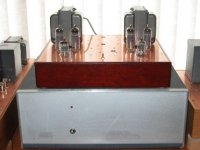
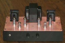
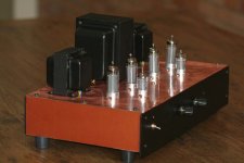
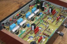
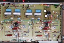
Here is my second and successfull tentative to build the
Baby Huey. In the first I tryed to build a compact layout but I had several problems like as heat dissipation, a bit of hum, difficult to mainteance, etc.
In this version I tryed to use almost all best practice
to build amplifier and I used copper enameled wire and
terminal strips to main wiring - thanks a lot to
rwellerson for tips and tricks as the use of the copper
rivets to fix the terminal strips on the epoxy fiberglass sheet.
I followed the original schematic with 12k global
feedback, 18K shunt feedback, 270R screen resistors (HT is in the upper side 350V) and 1000uF + 1uF in bias
block.
The amplifier is running dead quiet with wonderful sound!
Thanks gingertube!
Attachments
- Home
- Amplifiers
- Tubes / Valves
- EL84 Amp - Baby Huey