Oh... thank you. I think in this way its more organized and easyest to mae later modifications.
I have one doubt about the circuit. There is a wire in the CCS power output to ''0v at ecc83''. So, should i put this in the 12ax7 heater central tap (pin 9)? Its the only 0v i can see there... am i right, or in any 0v it will work (as it should work)?
I have one doubt about the circuit. There is a wire in the CCS power output to ''0v at ecc83''. So, should i put this in the 12ax7 heater central tap (pin 9)? Its the only 0v i can see there... am i right, or in any 0v it will work (as it should work)?
raidprotector said:Hmm :-(... lets see. I know a guy that does like that and have great results... when i could hear the sound i'll know, then if it sounds sucks i will take it off the 90 angles.
Hi raid,
You are doing fine indeed...
Your English is doing allright too, don't worry (it seems your language "teacher" here I know him very well...)
")
For your first try out on this difficult wiring technique I can say it is way ahead on some "industrial and professional" work, some of them well regarded and expensive tube stuff (have seen some "beautiful outside" far east products wiring that don't even get close to yours...)
Nice work and we would be curious for the resulting sound and electrical performance of this amp (the only thing I don't really like is the open circuitry, no chassis shielding: I've seen people doing that and giving up after a few trys because the level of noises, buzzes, hum and the like was unbearable... beware.
[ ]
Ricardo
P.S.
I would like to invite the friends in this space to take a look at my "site" and browse through the stuff I've been doing:
http://www.flickr.com/photos/vtr_products/
Thanks in advance!
raidprotector said:I have one doubt about the circuit. There is a wire in the CCS power output to ''0v at ecc83''. So, should i put this in the 12ax7 heater central tap (pin 9)? Its the only 0v i can see there... am i right, or in any 0v it will work (as it should work)? [/B]
There will be others more knowledgeable to comment, but since noone has so far, I'll step up and say that 0V at ECC83 means the ground/earth point at the ECC83 socket--usually where you ground your grid resistor--check back on gingertubes excellent recommendatios on earthing early on in this thread. Definitely not the heater CT, which is a different circuit altogether.
Hope you can follow me OK.
Cheers.
rwellerson said:
Hi raid,
You are doing fine indeed...
Your English is doing allright too, don't worry (it seems your language "teacher" here I know him very well...)
For your first try out on this difficult wiring technique I can say it is way ahead on some "industrial and professional" work, some of them well regarded and expensive tube stuff (have seen some "beautiful outside" far east products wiring that don't even get close to yours...)
Nice work and we would be curious for the resulting sound and electrical performance of this amp (the only thing I don't really like is the open circuitry, no chassis shielding: I've seen people doing that and giving up after a few trys because the level of noises, buzzes, hum and the like was unbearable... beware.
[ ]
Ricardo
P.S.
I would like to invite the friends in this space to take a look at my "site" and browse through the stuff I've been doing:
http://www.flickr.com/photos/vtr_products/
Thanks in advance!
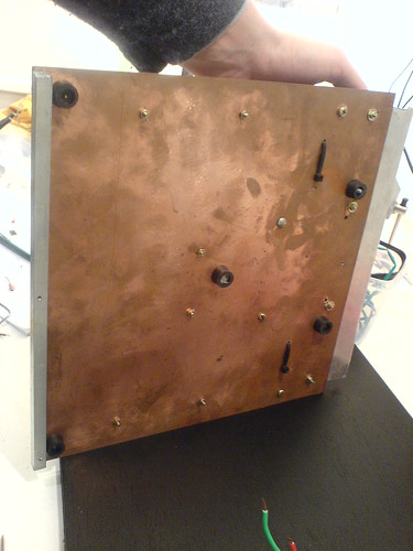
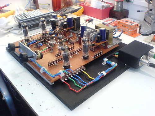
Thank you ricardo... your jobs inspirate mines. I'll put all the grounds in the down top of PCB (its a unused copper PCB) and my earth to (a 15 feet copper bar stick in the ground)... can you understand what i'm saying?
here go some pics of the CCS circuit board i made:
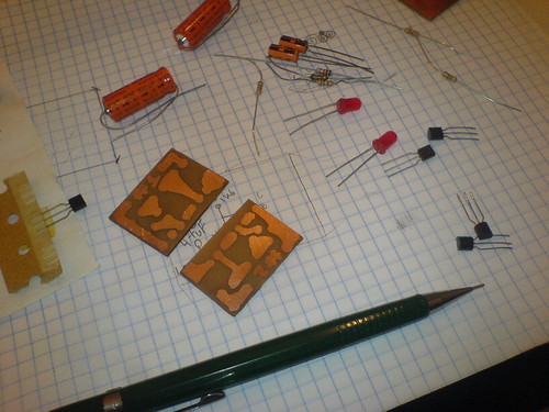
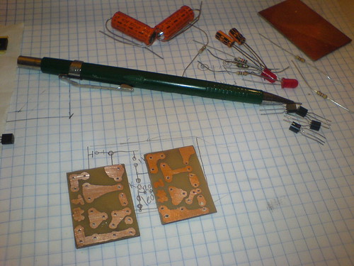
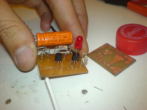
I'll test this 100uf/40v axial siemens for bypass... if it will be to much i can change him easily.
anatech said:Hi raidprotector,
Your capacitor is for bypassing the raw supply, right?
Can you post your schematic?
-Chris
Helle. The schematic is the same of gingertube, just change the capacitor.
Tony said:Hi raidprotector,
here is my unsolicited advice, you cand dab the pcb with clear plastic burnsih to protect the copper from getting tarnished..
Yes, thank you. I have a pcb varnish here that accept later welds (?understand?).
anatech said:Hi Ricardo,
Your workmanship is excellent! Amazing stuff, you have every right to be proud of your work!
Do some more. Possibly detail a build in a thread.
-Chris
Hi Anatech,
Thanks for your kind words.
It's a good idea to show those build details: give me some time for that.
[ ]
Ricardo
raidprotector,
I am very impressed with your build method.
Keep us informed of your progress.
Best Wishes
Ian (Gingertube)
P.S.
For those who have built a version of this amplifier using current sources in the output tube cathodes with bypass capacitors, here is another experiment for you to try:
Have a look at what Allen Wright did on this amp:
Notice that the 0V side of the cathode bypass capacitors do not go directly to 0V. The 2 0V ends of the capacitors are connected together and then have a 68 Ohm resistor to 0V. You can try this on a "Baby Huey". The fact that we use current sources rather than fixed resistors for the cathode biasing will not make any difference to this scheme.
This is a 3rd harmonic distortion suppression scheme and it is worth trying on a "Baby Huey". Try resistor values of between 33 ohms and about 150 ohms (use 2 watt resistors) to see what sounds best. You are listening for a smoother, less "Edgy" sound, particularly at higher frequencies. And of-course, let us know if you think it makes any difference, and if so, what resistor value sounds best to you.
I am very impressed with your build method.
Keep us informed of your progress.
Best Wishes
Ian (Gingertube)
P.S.
For those who have built a version of this amplifier using current sources in the output tube cathodes with bypass capacitors, here is another experiment for you to try:
Have a look at what Allen Wright did on this amp:
An externally hosted image should be here but it was not working when we last tested it.
Notice that the 0V side of the cathode bypass capacitors do not go directly to 0V. The 2 0V ends of the capacitors are connected together and then have a 68 Ohm resistor to 0V. You can try this on a "Baby Huey". The fact that we use current sources rather than fixed resistors for the cathode biasing will not make any difference to this scheme.
This is a 3rd harmonic distortion suppression scheme and it is worth trying on a "Baby Huey". Try resistor values of between 33 ohms and about 150 ohms (use 2 watt resistors) to see what sounds best. You are listening for a smoother, less "Edgy" sound, particularly at higher frequencies. And of-course, let us know if you think it makes any difference, and if so, what resistor value sounds best to you.
Friends,
I eventually got sick of Flickr albums, a very "nice" piece of s...
Now I transfered (and improved) my site to Multiply, much better stuff and user friendly tools, well organized space:
http://vacuumtuberesearch.multiply.com/
Hope surffing there is smoother now...
Thanks all,
Ricardo
I eventually got sick of Flickr albums, a very "nice" piece of s...
Now I transfered (and improved) my site to Multiply, much better stuff and user friendly tools, well organized space:
http://vacuumtuberesearch.multiply.com/
Hope surffing there is smoother now...
Thanks all,
Ricardo
Adam,
Not yet - too many projects and not enough time.
I had a couple of JADIS JA80 Monoblocks (80W Class A using 4 KT88 in each channel) and an 845 SET turn up for repair, a guitar amp to mod for cleaner sound and a guitar amp to design and build for a friend and a new EL84 Baby Huey half constructed as monoblocks but fixed bias this time so the mod is not applicable.
Starting to get a name around the local scene for being able to build/fix/modify amps and am having trouble saying NO - doesn't help that the local tube supplier keeps sending people to me, so my own projects are on hold till I can "clear the decks". I'll have to practice saying NO.
Hope to get back to the original EL84 Baby Huey to try this mod soon.
Cheers,
Ian
Ring-of-Two current source on Baby Huey
Ian,
I'm in the building process of a Baby Huey amp.
While breadbording and testing the ring-of-two current source of the EL84's, i noticed that they
don't have an auxiliary reference 12V-supply as usual, but the 5k6 resistor is connected to the collector of the MJE340 instead.
This makes a CCS that isn't spot-on the 38mA per EL84, but varies +/-4 mA depending on the voltage the CCS is exposed to on the EL84's cathode.
Is there any further thought behind that besides simplicity (=saving a reference supply) ?
My implementation gives the EL84 Bias-Blocks an auxiliary reference supply with a TL317.
As soon as my Baby-Huey is finished I'll report back (I'm progressing slowly due to lack of time).
Thanks for sharing your great work Ian.
Kind regards,
Yves
Yves,
I think you probably meant 4mA total variation, that is +/- 2mA as the applied voltage swings say 12 volts either side of the 12V DC level (which is the nominal bias voltage for the EL84).
In practice the cathode bypass cap will hold the voltage the CCS is exposed to at the EL84 cathode at a reasonably constant DC level (at the bias level) as the AC component will be shunted around the CCS by the bypass cap.
Taking that 5K6 back to an auxilliary +12V or similar supply, rather than to the cathode will certainly be an advantage if implementing the bypass cap modification suggested in a post above, because then the CCS could be considered to not be fully bypassed and some AC residual will appear across the CCS.
Thanks for raising this - it is worth having a think about.
Cheers,
Ian
Finally building this amp...
I've been experimenting with EL84 amps and am finally building a Baby Huey.
I'm using Dynaclone Z-565 OPT's. I have a Hammond 372JX - 300V@250mA which will push the voltage well above what is desired. Is it merely a matter of tweaking with higher value (and higher W rated) power resistors than the 47R's in the schematic or would there be a more suitabe method of dropping the HT? I have a few good chokes to choose from if necessary.
Best,
Adam
Adam,
Those 47R 2W in the original schematic were subsequently dropped to 4R7.
Its not a great idea to waste heat and power in dropping resistors in the main HT supplies.
Download PSUD2 from Duncan Amps Webpages and do some power supply modelling.
Ideal Voltage is about +320V. You really don't want to go above say +350V and even then I would change the 16 Ohm resistors in the EL84 cathode current sources to 18 Ohm to knock the idle current back from 38mA per tube to about 34 mA so as to keep total dissipation in the EL84s to around 12 watts.
Choke Input is a really good way to go as you can fine tune the final output voltage with a 0.5 to 2uF cap straight off the rectifier and before the choke. PSUD2 models this behaviour quite well. If you have seriously too much voltage you may like to even think about a tube rectifier although it may look a bit weird with a thumping great rectifier tube adjacent those little 9 pin tubes. 5AR4 would be the go.
I have 6V6 version of the Baby Huey running with a transformer similar to the 372 you quote. In that I use a 5R4 into 2uF polypropylene followed by a 8H 150mA choke for each channel and about 200uF of cap after each choke. (Actually I have 100uF electrolytic, 60uF polypropylene and 1 uF polypropylene all in parallel - so its about 160uF).
I also have an earlier version of the 6V6 which has a solid state rectifier into 2uF then a 2H 200mA choke followed by 100uF electrolytic. That then splits to the 2 channels each with 4R7 and 60uF polypropylene as the HT feed.
The tube rectified version with separate chokes feeding each channel perhaps sounds maybe 1% better.
If you go the SS rectifier direction that means that you can voltage double the 5V winding to generate the negative supply to return the front end diffamp current source to. That could also be generated using the bias tap on the HV winding.
Plenty of ways to skin a cat.
Cheers,
Ian
- Home
- Amplifiers
- Tubes / Valves
- EL84 Amp - Baby Huey