Hi Sharkey22,
Thanks for nice words about the PCB, I am not very good when I am soldering parts in point to point solution that's why I make PCB ! In addition with PCB manufacturing results are the same for each product made by different persons.
Regarding the Baby Huey, I have not decided yet the version that I will made, I was expecting some recommendation from Yves or Ian... I have also made the PCB for the MOSFET version and after some reading about the advantages of this solution I may decide to go this way ?
To summarize, I have 3 versions of PCB fir the Baby Huey:
1) the PLC86 (or ECL86) version which has been built and tested
2) the ECC83/EL84 version rev2 with the CCS and the bias blocks not yet produced
3) the ECC83/EL84 version rev3 with the fixed bias and MOSFET source follower not yet produced ( the schematic and the PCB are included in this message)
I will probably go to the last version because I will test it for a future project with auto bias and a quad EL84 output ! Many years ago I have been impressed by the Stingray amplifier from Manley Labs and I may try to test a quad EL84 Stingray II | Manley Labs but like Yves explain in his last comment he found some problems with the cathode bypass capacitors and since I don't want to trim 8 output tubes like him, I decided to give a try for an auto bias solution.
To answer yours question, the PCB is for one channel, you need to use two for a stereo system ( see photos on my first post ) and it is possible to mount big components on top for a fully enclosed version with a grid on top or big components can be soldered on the bottom side to fix the PCB under the top plate of a chassis with the tubes visibles.
Regards, Marc
Attachments
Just a better (more readable) of the schematic
Marc
I found an error: connecting point of R33 & R38 should be tied to -48V!
Regards,
Zoran
Thank you Zoran, indeed I have been too fast when I draw the schematic... I spend more time on it and I hope this time I didn't forget anything ? I have also added test point, changed transistors references and added a remark for 2W resistors. I don't know why R40 label disappear and C7 value (100uF 400V) as well ?
If there is no more error, I will send the file to the PCB manufacturer this week end")
Regards
If there is no more error, I will send the file to the PCB manufacturer this week end
Regards
Attachments
Thank you Zoran, indeed I have been too fast when I draw the schematic... I spend more time on it and I hope this time I didn't forget anything ? I have also added test point, changed transistors references and added a remark for 2W resistors. I don't know why R40 label disappear and C7 value (100uF 400V) as well ?
If there is no more error, I will send the file to the PCB manufacturer this week end
Regards
I recommend a LTP CCS as drawn in post #602, with 2 LEDs. Only minor changes in your schematic and PCB are required. Also, R9 and R10 should be 2W type. Consider rising R20 & R21 values to 1MOhm to make LTP job easier.
Happy building!!!
Regards,
Zoran
Thanks for your comments Zoran. I changed R20 & R21 to 1M and I also changed R16 & R17 to 15K & 10K to limit the current in the red LED. What is the advantage of a blue LED instead of a red one and a green LED in place of the resistor ?
For R9 & R10 (or R29 & R30) 2W is already recommended in the text above the resistor, VISHAY CPF2 or TE connectivity RR2 will fit very well in the layout (9 mm body).
Regards,
Marc
For R9 & R10 (or R29 & R30) 2W is already recommended in the text above the resistor, VISHAY CPF2 or TE connectivity RR2 will fit very well in the layout (9 mm body).
Regards,
Marc
Thanks for your comments Zoran. I changed R20 & R21 to 1M and I also changed R16 & R17 to 15K & 10K to limit the current in the red LED. What is the advantage of a blue LED instead of a red one and a green LED in place of the resistor ?
For R9 & R10 (or R29 & R30) 2W is already recommended in the text above the resistor, VISHAY CPF2 or TE connectivity RR2 will fit very well in the layout (9 mm body).
Regards,
Marc
Well, I guess #602 post CCS is supposed to be better
It is described in Morgan Jones "Valve Amplifiers" 4th ed. page 140. Regards,
Zoran
Marc, My interest in the PCB version are for the same reasons, ie. my point to point skills and experience are rather limited. I am sure opinions vary on the best Huey variant but it seems to me that the prefered version is the CCS and Bias block version. Ian (Gingertube) has been very helpful with advice for me and even designed me a custom HT power supply with choke. I am sure if you PM him or Yves they will offer you solid advice and opinion regarding the best Huey design with all the best tweeks. Regards (another) Ian.Hi Sharkey22,
Thanks for nice words about the PCB, I am not very good when I am soldering parts in point to point solution that's why I make PCB ! In addition with PCB manufacturing results are the same for each product made by different persons.
Regarding the Baby Huey, I have not decided yet the version that I will made, I was expecting some recommendation from Yves or Ian... I have also made the PCB for the MOSFET version and after some reading about the advantages of this solution I may decide to go this way ?
To summarize, I have 3 versions of PCB fir the Baby Huey:
1) the PLC86 (or ECL86) version which has been built and tested
2) the ECC83/EL84 version rev2 with the CCS and the bias blocks not yet produced
3) the ECC83/EL84 version rev3 with the fixed bias and MOSFET source follower not yet produced ( the schematic and the PCB are included in this message)
I will probably go to the last version because I will test it for a future project with auto bias and a quad EL84 output ! Many years ago I have been impressed by the Stingray amplifier from Manley Labs and I may try to test a quad EL84 Stingray II | Manley Labs but like Yves explain in his last comment he found some problems with the cathode bypass capacitors and since I don't want to trim 8 output tubes like him, I decided to give a try for an auto bias solution.
To answer yours question, the PCB is for one channel, you need to use two for a stereo system ( see photos on my first post ) and it is possible to mount big components on top for a fully enclosed version with a grid on top or big components can be soldered on the bottom side to fix the PCB under the top plate of a chassis with the tubes visibles.
Regards, Marc
Hi (the other) Ian ,
PCB's are in production since Saturday ! Finally after more reading I decided to build version 3 because it will be a test platform for a quad EL84 version with auto-bias and I want to avoid eight "boutique" decoupling capacitors in the output stage... Beside that I have read good articles about MOSFET follower and I want also to give it a try. I have produced 5 boards and if the first set is working well, I could sell you one (mono) or two boards (stereo). I will send photos when the prototype will be built. I don't know how we can exchange mail address without the risk of being spammed on this forum ?
I am also working on some kind of quasi-universal power supply board with High Voltage and heater DC regulators as well as bias servo for a quad output tube output (based on Norman L. Koren TENA project (even if he say that it is not for beginners, that's why I will start with EL84 before to think about 6550 or EL34...).
Regards, Marc.
, PCB's are in production since Saturday ! Finally after more reading I decided to build version 3 because it will be a test platform for a quad EL84 version with auto-bias and I want to avoid eight "boutique" decoupling capacitors in the output stage... Beside that I have read good articles about MOSFET follower and I want also to give it a try. I have produced 5 boards and if the first set is working well, I could sell you one (mono) or two boards (stereo). I will send photos when the prototype will be built. I don't know how we can exchange mail address without the risk of being spammed on this forum ?
I am also working on some kind of quasi-universal power supply board with High Voltage and heater DC regulators as well as bias servo for a quad output tube output (based on Norman L. Koren TENA project (even if he say that it is not for beginners, that's why I will start with EL84 before to think about 6550 or EL34...).
Regards, Marc.
I don't know how we can exchange mail address without the risk of being spammed on this forum ?
Send a Private Message.
--
Boards
Hii Marc, it sounds as though the boards you have chosen to make can be used for a pair OR a quad of EL84's per channel. My o/p transformers are made for a pair of 84's but are hugely over sized and can probably handle a quad setup if impedence is compatible, same for my power supply. I look forward to seeing your results. I have sent you a PM with my contact details. Regards Ian.
Hii Marc, it sounds as though the boards you have chosen to make can be used for a pair OR a quad of EL84's per channel. My o/p transformers are made for a pair of 84's but are hugely over sized and can probably handle a quad setup if impedence is compatible, same for my power supply. I look forward to seeing your results. I have sent you a PM with my contact details. Regards Ian.
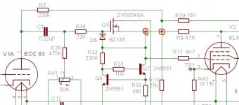
Thank you Jane and Ian for the feedback... Of course there is no connection between Q5 & R9 and Q6 & R10 !!! I have made a mess during the schematic redraw... The good news is that these two tracks on the PCB are both using one of the only 3 vias needed during routing, therefor I will just have to drill two vias with a larger diameter to cut the connection
Normally PCB's should arrive today, I will keep you updated when they will be built.
For the other Ian (sharkey22), the boards are only for two EL84, I have started a new design for the quad EL84, but I want to test the MOSFET follower before to go ahead with this new project and the mistake found in the actual board tell me to be more careful and to check twice my design before to go in production with the PCB. More detail on the quad EL84 will be available later, I have already made the schematic and a draft of PCB but with 4 trimmers for the bias and in the final version I want to use some kind of auto-bias, that is the reason for the design of the power supply board...
Rgds,
Marc
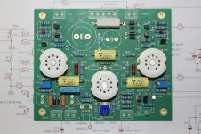
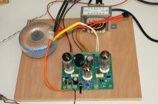
Received the PCB and started assembly... I learn a lot with this project, since the ECL86 version run smoothly without any error I was too confident and I made several mistakes on this version
Beside the schematic error which are to be corrected on the PCB at the two locations indicated by the yellow arrows, I made several other stupid mistakes, I used the same pattern for 2W resistors than for 0.6W and if the length was OK, I did not see that the lead were 1 mm instead of 0.8 mm ! Another error that hopefully I found before soldering was the pin-out of the 2N5551, I took the same BC547 library that I used for the ECL86 version, but US and European pin out are not the same, collector and emitter are reversed !!! This is why on the second photo the transistors are not mounted like the serigraph
I am waiting to receive the MOSFET to finish assembly. As the board is now, it is possible to place the big capacitors under the PCB if the tubes should be on top of the chassis instead of in a box.
Lesson learned, for the next project I will make a triple check before to send the PCB to the manufacturer...
Marc
Attachments
One more Baby Huey is playing
Mono version is playing...
This is probably the most complicated small amplifier that I have ever built or even seen ! Now it is playing in mono (second channel not built yet) and the sound is also very good but very close to the ECL86/PCL86 version at low to medium level, the principal difference that I have found is at higher level were the EL84 version keep a better control of the loudspeaker (I don't think it is because of the tubes but probably the fixed bias with the source follower does a better job than the previous version, like Ian say in an older post).
I have added two photos, the first one show the board mounted without the tall components like capacitors and connectors for a chassis version under the top plate, while the second one is finished, and playing music, for a boxed version mounted on the bottom plate (sorry for my English I don't always find the exact word but I hope you understand anyway ?). As you can see I have built the version with feedback from the plates and current source with the blue LED. By the way the MOSFET were also reversed, hopefully I check before soldering, lesson learned...
Have a nice week-end,
Marc
Hi,
I have made some more test on the EL84 Baby Huey and I replaced the OT RTU-101 by the Hammond 1609 (10k primary) that was used in the PCL86 version and, bingo, the result is much better, the sound is not as hard as before, I didn't expect that the output transformer could give such a difference, but there could be a problem with the wiring of the secondary of the RTU-101 because there are 3 pairs of output and if they are in parallel for 4 ohms and in serial for 16 ohms, there is a strange connection schema for 8 ohms (what I have used) ! I may try again later with the 4 ohms connection...
All version (PCL86 & EL84) run perfectly without global feedback, I have respectively 15k and 18k shunt resistors , I have made several voltage measures with different value for the power supply:
PCL86:
230 V AC > 296 V DC with 10.75 V cathode
252 V AC > 321 V DC with 11.80 V cathode
275 V AC > 353 V DC with 12.95 V cathode and about 28 mA bias
EL84:
263 V AC > 339 V DC and about 35 mA bias
Now I have to build the second channel to enjoy the EL84 version in stereo
Cheers,
Marc
Stereo Baby Huey EL84 fully working...
Now the two channels are playing wonderfully
The first one was built with the blue and green LED while the second one used the more traditional red LED with resistors (see photos), I cannot find any difference when I listen CD but the voltage on the 12AX7 is of less than 80V in the first case and of 157V in the second case, after reducing R18 from 1.5k to 820 ohms
May be Ian (Gingertube) or Yves can explain that and why I cannot change the voltage with the blue LED when I change the value of the resistors ? I read article on that subject in several books but did not find an easy way to calculate the resistors value to define the required current ?
I build the second channel with the big components (mainly capacitors) under the PCB to allow to fix the board under the chassis with the tube visible on the top, this give also the advantage to avoid the proximity of the very hot tubes and reduce the temperature for capacitors (better for longer life)... I will have to build a third board to put my amplifier in a chassis.
For those interested, I have made the correction on the schema and added more information about voltage and components value.
I like the MOSFET solution and I will definitely use it for a next project...
Cheers,
Marc
Attachments
Less than 80V is too low. 157V is OK but I usually aim for say 180 to 200V.
R18 adjusts the current source set current and so should adjust the 12AX7 anode voltages. Increas R18 to reduce current and raise teh 12AX7 anode voltages.
R16 sets the current through the Current source reference LEDS. 15K is OK, I would probably use 22K or 27K but close enough, you don't need any more than say 2mA thru' the LEDS.
What is R17 doing? It should not be there. I would delete it.
Cheers,
Ian
Last edited:
- Home
- Amplifiers
- Tubes / Valves
- EL84 Amp - Baby Huey