Monitoring Output tube balance
Hi all,
Still collecting the bits for my baby huey, and want to put some meter on to monitor and balance the CCS. Thinking of using the alternative CCS based on the DN24560 (as its adjustable), and have found these great looking panel meters.
Question:
Is it better to wire a mA meter in series with the CSS, or a mV meter across a 1 ohm resistor which is in series with the CCS?
I ask this from the perspective of sound quality, does the inductive load of an mA meter in series have the potential to screw up the quality of the design? I like the idea of actually measuring the current than the voltage, but not at the expense of the sound...
Thanks in advance
Malcolm
Hi,
I am another diyer wanting to build this Baby Huey amp. A bit lost among the various updates brought along this thread, could someone direct me towards the final version aka the best sounding version?
- Does the wiki page written by Bas Horneman represents the final version?
- The speakers I want this amp to drive are Fostex Fe207, any experience with those?
- I'd be interested in a mono bloc schematic if it exists.
- Is there an existing list of components? I am staying in France and would like to order the lot to get started soon. (my SS Onkyo amp is dying)
Thank you very much for help and congratulations to those who built very nice unique amplifiers!
Anyone to get me started?
My understanding is that the CCS are fully bypassed with caps so the CCS should have minimal impact on the sound of the amplifier. As such either way will work fine, and the DN2450 is more than capable of coping with a bit of inductance.
However, the bias CCS functions to fix the current through the output valves so you should expect to see no need for adjustment at any time so a bias adjustment meter is a bit superflous.
Shoog
However, the bias CCS functions to fix the current through the output valves so you should expect to see no need for adjustment at any time so a bias adjustment meter is a bit superflous.
Shoog
No. It just shows the easier to build version.Does the wiki page written by Bas Horneman represents the final version?
Not really. Because none of the parts are hard to get really...and most parts are pretty standard.Is there an existing list of components?
Just build two power supplies. The extra current won't hurt.I'd be interested in a mono bloc schematic if it exists.
I don't have experience with that....but my suggestion would be to build a single ended amp for those. Something like the RH84. BUT that is just me. With my Bastanis Prometheus...I prefer single ended to pushpull. (So far...who knows what the future might bring)The speakers I want this amp to drive are Fostex Fe207, any experience with those?
Last edited:
A general question here....I'm looking for suggestions as to what would be a good tube preamp that would compliment the Baby Huey. Is lots of drive and/or gain needed for the Baby Huey? I already have a modified Bottlehead Foreplay (12AU7 version) and I am happy with it but as always I'm looking for the next evolutionary step....
Your suggestions are appreciated
Thanks
Frank M
Your suggestions are appreciated
Thanks
Frank M
Hi George (Geosto), On your creation of the BH (Quad EL84) what does R6 do on the input and is it log or lin?
malcolm
Hi Malcolm,
R6 adjust the balance between the positive and the negative signal.
By adjusting it, you can make the 2nd harmonic as low as possible.
No two tubes have exact the same characteristics.
I use a lin pot bud it is not critical.
If you swap R21 for the same pot than you can also adjust the gain of the amp
") in my case that was necessary.
in my case that was necessary.Notes for the 6SL7/6V6 version in the picture back a few posts.
Grab the post #602 schematic.
The common resistor in the 6V6 cathodes is 56R in lieu of the 10R shown for EL84.
The 390R in the current source loads on in the mosfet source followers is 220R to increase the current in the source followers to 3mA.
The 220K in these current sources reduces to 47K .
The 47K + 16K + 47K between the output tube anodes is 39K + 13K + 39K instead. 6SL7 anode loads are still 220K as shown for the ECC803S
There is a 10R + 2u2 zobel added across the 4 Ohm speaker output.
The +56 Volt rail is now +33V
The -48V rail is now -70V
The -45V for the diffamp CCS is now -33V
B+ is +340V
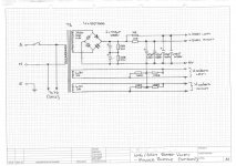
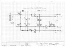
Here are the power supply schematics, Note I used a second small tranny (4.5VA) to generate the low voltage supplies.
Grab the post #602 schematic.
The common resistor in the 6V6 cathodes is 56R in lieu of the 10R shown for EL84.
The 390R in the current source loads on in the mosfet source followers is 220R to increase the current in the source followers to 3mA.
The 220K in these current sources reduces to 47K .
The 47K + 16K + 47K between the output tube anodes is 39K + 13K + 39K instead. 6SL7 anode loads are still 220K as shown for the ECC803S
There is a 10R + 2u2 zobel added across the 4 Ohm speaker output.
The +56 Volt rail is now +33V
The -48V rail is now -70V
The -45V for the diffamp CCS is now -33V
B+ is +340V
Here are the power supply schematics, Note I used a second small tranny (4.5VA) to generate the low voltage supplies.
Attachments


Last edited:
Black Gate caps alternative.
Hi Gingertube, I notice you specify Black Gates in the power supply, as these are now hard to find and very expensive what would you recommend as a substitute, how about the Nichicon MUSE KZ series? Does anyone have experience and opinions of the Nichicon muse range?
Hi Gingertube, I notice you specify Black Gates in the power supply, as these are now hard to find and very expensive what would you recommend as a substitute, how about the Nichicon MUSE KZ series? Does anyone have experience and opinions of the Nichicon muse range?
. Hi George (Geosto), On your creation of the BH (Quad EL84) what does R6 do on the input and is it log or lin?
malcolm
Last edited by malcolmfraser; 27th April 2013 at 12:03 PM.
Malcolm, I always wanted to know - did you ever end up finding those trousers ?
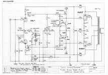
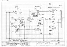
In post #1349, Ian was kind enough to post the various changes made to the 6SL7-6V6 version of the Baby Huey. I took that info and added it to the older 6SL7-6V6 version from post #602.
So here, for the record (and given a check by Ian), is the compleat collection of schematics for the current-issue 6SL7-6V6 Baby Huey.
(I want to build this one with smooth plate Telefunken ECC83 and Russian 6P1P-EV)
So here, for the record (and given a check by Ian), is the compleat collection of schematics for the current-issue 6SL7-6V6 Baby Huey.
(I want to build this one with smooth plate Telefunken ECC83 and Russian 6P1P-EV)
Attachments


Last edited:
I have a question about the -33V supply and how it is connected to the 6SL7 tails.
Looking at the schematic, I see it bypassed to ground by a 1000uF 50V capacitor. Then it goes from there to the junction of a 2k2 resistor and a 33k resistor, which connects to the -70V supply.
I have to admit that I'm baffled by this. I guess I'm showing my lack of understanding of voltage dividers, etc.
I see how the -70V feeds the bias network (ganged 50k pot and 1M2 resistors to the gates of the ZVN0545A's), but that shouldn't be drawing appreciable current.
I assume the -33V rail connects at the junction of the cathode of the blue LED, 1k5 resistor and 1000uF cap, which connects to the BC546B ccs.
So, what is that 2k2 resistor doing there, connecting the -33V rail to the -70V rail? I don't get it...
--
Last edited:
Drewaudio,
negative rail for the source follower needs to be approximately 3 times the bias voltage such that the signal to the output tube grid can pull down far enough to definitely cut off the output tube. For 6V6 that requires around -60V minimum whereas for EL84 -35V would probably do.
rogon,
A bit confusing, sorry. The new power supply drawings show the " local for each channel" power supply decoupling components, ignore the duplicates on your markup. That is,
the 2K2 and 1000uF from the -70V are deleted and the point you have marked -33V comes direct from the power supply where you will see that this supply has 4K7 + 220uF decoupling instead. Hope that clears this up.
6L6,
The 12AX7/EL84 fixed bias version is the post #602 schematic which rogon has marked up for 6V6. The change to the source follower current (increased to 3mA, see the 220R and 47K markups) are recommended for this version too. You could also use just the +/-33V part of the power supply schemtic above, reduce the 4K7 resistors to say 1K to give a few more volts.
The "simple" CCS biased version schematic is way back on page 1
Each of the amps I have built ended up with a slightly different power supply determined by what transformer(s) I had on the shelf at the time.
The "simple" BH requires just the B+ and a "non critical" negative rail for the diff amp front end (anywhere from -3V to the voltage rating of the transistors in the cathodes)so is also "simple".
The Fixed bias versions requires a negative rail for the bias supply and for the source follower return and a low positive rail for the mosfet drains. That right hand side schematic in rogon's post above is my preferred method for generating those supplies by using a small extra transformer (but plenty of ways to skin the cat)..
Cheers,
Ian
Last edited:
Is there a similar set of schematics, with everything drawn out, for the 12AX7/EL84 version?
I was just reading it yesterday, not quite sure if all the schematics are the latest version though... should be close.
Baby Huey PP EL84 amplifier - diyAudio
Jaz
Yes, Baz's wiki (link in post above) is the place to look for the "simple" Baby. My protoptype still looks like this after being in and out of my system over the last few years.
That schematic matches my unit exactly except that I have a 1K8 + 2n2 zobel wired across the 16K shunt feedback set resistor. That "knocks off" a bit of high frequency feedback to PRE-compensate for the loss due to the 12AX7 diff amp driving the Miller Capacitance of the output tubes.
Cheers,
Ian
That schematic matches my unit exactly except that I have a 1K8 + 2n2 zobel wired across the 16K shunt feedback set resistor. That "knocks off" a bit of high frequency feedback to PRE-compensate for the loss due to the 12AX7 diff amp driving the Miller Capacitance of the output tubes.
Cheers,
Ian
- Home
- Amplifiers
- Tubes / Valves
- EL84 Amp - Baby Huey