Michael,
Yes the UL Connections are the same in both cases. I had thought to post these "results"/opinions on the E-Linear thread. That is because when using the UL taps as the feedback source the circuit trends toward E-Linear at higher feedback levels.
When I first tried using the UL Taps as the source of the balanced shunt feedback (in lieu of the EL84 anodes) I did a calc. to set resistor values to ensure the same level of feedback and then confirmed it by Zout measurement. These are the values I posted (post 602 and post 604 for the 2 variants).
This may have something to do with the low damping factor (Zout of the BH is more like most SE Zout values at around 2 Ohms) BUT I'm beginning to suspect it has to do with the distribution of leakage inductances and interwinding capacitances in the Output Transformer.
We are looking for the last 2 to 5% here and at the same time trying to keep the "simple" and "inexpensive" design philosophy.
That is the reason I was looking at VoltSeconds work on resonances in Output Transformers to see if I could devise a "scientific" method for setting anode to screen zobels or determining if indeed that anode to screen was the best place for such zobels, perhaps anode to anode or each anode to B+ may have been more suitable. In my frustration I am almost ready to sit down with pad and pencil and do amplitude and phase plots for each primary and secondary transformer connection. I don't see any "short cut" method to investigate this more thoroughly.
ASIDE: Plus there is a little voice in the back of my head saying "you are an Electronic Design Engineer, stop looking for shortcuts and do this properly in an Engineering fashion".
This is also aimed at forming my own view on the age old arguement as to whether UltraLinear has some fundamental limitation (Yves M and Allen W are just 2 folk who seem to think so) or whether no one has properly come to grips with the transformer interactions and so it is the implementation of UL and not the actual scheme which may have some limitation, that is, that it is usually done too simply, without addressing OT "warts". Fritz Langford Smith (of RDH fame) did a couple of articles on Ultralinear and he just stated that anode to screen zobels were "required" with no further explanation. Then for the next 50 years designers built Ultralinear amps without
these zobels (95% of them anyway).
A bit of a rave - hope there is something of interest in it.
Cheers,
Ian
Last edited:
Bas,
My remark is related to the schematics on post #602 and #604.
#602: the local feedback comes from the EL84 anode tap.
#604: the local feedback comes from the EL84 UltraLinear tap.
During my experiments #602 sounded better to me and is stable without additional tuning (better focus on voices and balanced soundstage).
#604 seems to be quite dependant on the brand of OPT and impedance variations of the speaker. A zobel from anode-tap to UL-tap, as described by Gingertube, was
necessary in my amp to tame the spurious oscillations with a square-wave test signal (see my previous posts with the scope shots).
Note that no EL84 triode connection is involved here, the BabyHuey-topology is always connected to the UL-tap of the OPT, only the ECC83 anode supply comes either from the anode tap or Ultralinear tap.
Kind regards,
Yves
What does that mean in simple language? That triode connection is the way to go?
My remark is related to the schematics on post #602 and #604.
#602: the local feedback comes from the EL84 anode tap.
#604: the local feedback comes from the EL84 UltraLinear tap.
During my experiments #602 sounded better to me and is stable without additional tuning (better focus on voices and balanced soundstage).
#604 seems to be quite dependant on the brand of OPT and impedance variations of the speaker. A zobel from anode-tap to UL-tap, as described by Gingertube, was
necessary in my amp to tame the spurious oscillations with a square-wave test signal (see my previous posts with the scope shots).
Note that no EL84 triode connection is involved here, the BabyHuey-topology is always connected to the UL-tap of the OPT, only the ECC83 anode supply comes either from the anode tap or Ultralinear tap.
Kind regards,
Yves
Michael,
Yes the UL Connections are the same in both cases. I had thought to post these "results"/opinions on the E-Linear thread. That is because when using the UL taps as the feedback source the circuit trends toward E-Linear at higher feedback levels.
When I first tried using the UL Taps as the source of the balanced shunt feedback (in lieu of the EL84 anodes) I did a calc. to set resistor values to ensure the same level of feedback and then confirmed it by Zout measurement. These are the values I posted (post 602 and post 604 for the 2 variants).
This may have something to do with the low damping factor (Zout of the BH is more like most SE Zout values at around 2 Ohms) BUT I'm beginning to suspect it has to do with the distribution of leakage inductances and interwinding capacitances in the Output Transformer.
We are looking for the last 2 to 5% here and at the same time trying to keep the "simple" and "inexpensive" design philosophy.
That is the reason I was looking at VoltSeconds work on resonances in Output Transformers to see if I could devise a "scientific" method for setting anode to screen zobels or determining if indeed that anode to screen was the best place for such zobels, perhaps anode to anode or each anode to B+ may have been more suitable. In my frustration I am almost ready to sit down with pad and pencil and do amplitude and phase plots for each primary and secondary transformer connection. I don't see any "short cut" method to investigate this more thoroughly.
ASIDE: Plus there is a little voice in the back of my head saying "you are an Electronic Design Engineer, stop looking for shortcuts and do this properly in an Engineering fashion".
This is also aimed at forming my own view on the age old arguement as to whether UltraLinear has some fundamental limitation (Yves M and Allen W are just 2 folk who seem to think so) or whether no one has properly come to grips with the transformer interactions and so it is the implementation of UL and not the actual scheme which may have some limitation, that is, that it is usually done too simply, without addressing OT "warts". Fritz Langford Smith (of RDH fame) did a couple of articles on Ultralinear and he just stated that anode to screen zobels were "required" with no further explanation. Then for the next 50 years designers built Ultralinear amps without
these zobels (95% of them anyway).
A bit of a rave - hope there is something of interest in it.
Cheers,
Ian
Great information there. I looked back in the thread and I get it now.
what an interesting journey
Thanks!
Michael
Hi Yves,Bas, do you plan to move at ETF09 ?
http://www.triodefestival.net/index.php?page=etf-2009
Unfortunately not. I hope to go to one....one day.
")
Thanks for that lucid clarification!Note that no EL84 triode connection is involved here, the BabyHuey-topology is always connected to the UL-tap of the OPT, only the ECC83 anode supply comes either from the anode tap or Ultralinear tap.
Well I’ve moved the feedback from the UL taps to the anodes. I’ve noticed a much larger sound stage, with possibly looser bass/mid. It really is a much different sound, using the UL taps with a zobel across the speaker taps the sound was nearly identical to a SS amp. (I built an A/B amp switch so I could quickly move between the amps) . With the anode feedback it has a much different feel than the SS.
I’m going to go ahead and add the 2n2F-1kO zobels between the anodes and screen taps. I’m not sure how humps in the 30-60khz range would manifest to my ears which can’t hear much beyond 25khz, but I don’t think it could hurt.
I’m going to go ahead and add the 2n2F-1kO zobels between the anodes and screen taps. I’m not sure how humps in the 30-60khz range would manifest to my ears which can’t hear much beyond 25khz, but I don’t think it could hurt.
Guys,
Just a quick update.
Note Bas has started a wiki for a Baby Huey build.
I have chased the shunt feedback from the UL taps, instead of the EL84 anodes, down its rabbit hole as far as I could and have finally abandoned it. I tried all sorts of feedback levels and output tranny compensation schemes and it is just one of those ideas which did'nt pan out.
I'm back to taking the feedback from the EL84 anodes as in the original design.
I have left the 1K + 1nF zobels between the anode and ultralinear taps on the Hammond 1608 output transformers in.
Cheers,
Ian
Last edited:
Ian,
I've been meaning to ask for a while what the 470ohm resistors are for in the driver stage? Since the CCS determines the current through them.
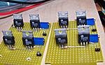
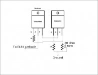
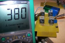
Also. I've built the bias blocks as shown in the attachments. Just to be sure. They should work right? (Just have to bypass them still).
Kind regards,
Bas
I've been meaning to ask for a while what the 470ohm resistors are for in the driver stage? Since the CCS determines the current through them.
Also. I've built the bias blocks as shown in the attachments. Just to be sure. They should work right? (Just have to bypass them still).
Kind regards,
Bas
Attachments
Bas,
The 1K pot is to set balance in the diff amp. The resistance in the triode cathode degenerates the tube gm (Ia/Vgk). Sweeping the pot wiper from side to side varies the amount of degeneration on each of the 2 triodes until they match. This is the minimum distortion condition for the diff amp. As we don't want to throw away gm un-necessarily we don't want those resistance values too high - just high enough to be able to adjust for matching behavior.
For a random sampling of 12AX7 and ECC803S that I had, 1K was too much, 100R was'nt quite enough so I dropped the 470R on each side of the 1K pot which effectively makes that pot about 600 Ohms (about 300 Ohms each side of the wiper when set to the middle). If you can find a 500 Ohm pot then you can use that, in fact if you select a tube with matching triodes then you can get away with a 100 Ohm pot.
Hope this explains what those 470 Ohm resistors are doing.
Cheers,
Ian
Merci!Check for the lowest THD or simply for the same voltage at the plates of the triodes.
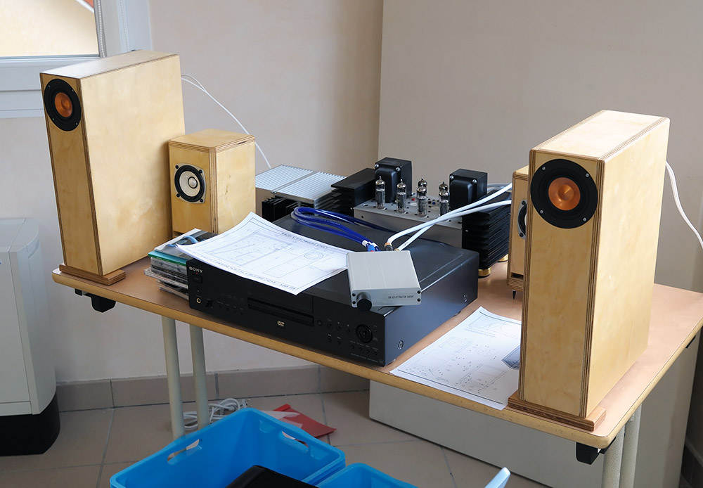
Indeed, my Baby Hueys. Well spotted Bas.
Unfortunately I ran short on time and couldn't bring my unfinished fixed-bias Baby Hueys.
My setup was way the smallest one on ETF and I had to share the room
with two guys that had a large system with AER an Podzus drivers, so I didn't
insist. But as my setup was up-and-running in 15 minutes I had my demo-time at the arrival day.
Same conclusion as every year: Size matters at ETF.
Kind regards,
Yves
. . .
Same conclusion as every year: Size matters at ETF.
"Les petits ruisseaux font les grandes rivières !"
Litterally : Small brooks make large rivers.
We may consider grouping ourselves . . . next year !
Yves.
Yves, was Yves (jeez that's confusing already - read on for more confusion) talking about the size of his "equipment" (so to speak"Les petits ruisseaux font les grandes rivières !"
Litterally : Small brooks make large rivers.
We may consider grouping ourselves . . . next year !
Yves.
) rather than the size of the group (he was on his own)?Yves has a regulated PSU amongst other things...so that may account for the heatsinks.anyone know what the enormous heatsinks are for?
Attachments
Last edited:
- Home
- Amplifiers
- Tubes / Valves
- EL84 Amp - Baby Huey