The "Baby Huey" concept works best with higher gm Output tubes - because the feedback it uses basically trades output tube gm for reduced rp.
It will therefore work well with ECL86, EL84, EL34, KT77, KT88 etc.
It will also work (but not as well) with lower gm tubes such as 6V6 and 6L6. I've built a number of lovely 6V6 based versions.
Cheers,
Ian
It will therefore work well with ECL86, EL84, EL34, KT77, KT88 etc.
It will also work (but not as well) with lower gm tubes such as 6V6 and 6L6. I've built a number of lovely 6V6 based versions.
Cheers,
Ian
Hammond Trannies for Baby Huey
In my on-going efforts to "convert" the youth of the world to Hollow State my apprentice at work has just finished building a fixed bias version of the Baby Huey for his home HiFi.
He wanted to use a single power supply for both channels and use readily available Hammond Trannies.
Here is what we came up with for his amp:
Power Supply (for 2 channels).
Power Transformer - Hammond 370HX (275-0-275 V @ 200mA).
Solid State Rectifier Diodes (Ultrafast Soft Recovery)
"C-L-C" arrangement power supply.
10uF/900V Polypropylene first capacitor.
Hammond 158S (1.5H 250mA 60 Ohms DCR) choke
470uF/450V final electrolytic with 5uF/900V polypropylene in parallel for the 2nd capacitor.
This gives a rock solid 330V rail - just right.
Hammond 1608 Output Trannies.
Notes:
The 900V polypropylene for the first capacitor is an overkill. You don't need a fantastic quality cap in this position.
The Ripple Current for this capacitor (according to PSUD2) is 320mA RMS
A Panasonic ED 10uF/450V has a 350mA RMS ripple current rating and could be used instead.
BUT
I would instead RECOMMEND using 2 off Panasonic ED 22uF/200V in series, with 220K voltage share resistors (1 or 2 watt) across each capacitor. These caps have 600mA ripple current rating which means a far longer lifetime.
For the cap in parallel with the 470uF/450V second capacitor, any 630V rated film cap of 2.2uF or 4.7uF would do. Polypropylene for preference but even polyester will be better than no parallel cap.
This supply would suit either the original (CCS biased) or the fixed bias versions of the Baby Huey.
Cheers,
Ian
Ian: A question about ripple current in PSUD....
I just modeled your PS values above, and I am curious how you get ripple current for C1 off of the model. None of the I(x) current curves are anywhere close to 320ma so I'm assuming that there is a calculation to get ripple current?
thanks
I just modeled your PS values above, and I am curious how you get ripple current for C1 off of the model. None of the I(x) current curves are anywhere close to 320ma so I'm assuming that there is a calculation to get ripple current?
thanks
After you run the sim look in the Results Table for I(C1). The right most column has the RMS Amps values in it - that is the Ripple Current.
Plugging in all of thh transformer, cap, inductor etc, values in my post above then I(C1) was reported as 321.33mA RMS.
I used current source load at 140mA (35mA idle current each off the 4 EL84s) with a step to 180mA at 1.5 seconds to see what will happen when you run the amp really hard.
To check I just re did the sim but looked at values for 2 seconds after a startup delay of 1 second (same load step from 140mA draw to 180mA draw) at 1.5 seconds- that gave a ripple current of 260.9mA.
That is a more realistic value, since the initial capacitor charge currents at power on are then not included in the "operating" ripple current calc.
That means that the single 10uF/450V Panasonic ED (360mA ripple current rated) would be satisfactory. No need to go for the 2 lower voltage units in series.
The ripple current calculation is not really simple - its one of those formula where you take the Root Mean Square value of the charge current and the discharge current but where there is an adjustment according to the charge time and discharge time ratio.
There is a "White Paper" on it on the EPCOS capacitor Website if you are all that interested. It also covers how to then calculate capacitor expected lifetime. Basically there is an inverse square relation ship with Ripple Current. Halve the ripple current (or use a cap with 2 x the ripple current rating) and you will get 4 times the life expectancy.
Cheers,
Ian
adamus said:a rather unglamourous shot, without knob or the baseplate screwed on.
An externally hosted image should be here but it was not working when we last tested it.
Adam, do you have the schematic you used for the PS?
R
adamus said:I'll sketch one up for you. but it is basically full wave with grounded ct, then 6uf then 5h choke, then 220uf.
Cheers - Dont worry about the sketch up.
Brit01 said:I'm curious and have a newbie question.
What are you guys using as the source signal here with the baby huey designs?
linestage/pre-amp? If so what designs and how much gain/Zo?
CDP(2V)?
Vinyl?
CD player or squeezebox through an Aikido 6BQ7/6DJ8
CD player or squeezebox through an Aikido 6BQ7/6DJ8
That's good to hear boywonder. I was thinking my Aikido was going to have too much gain with a CDP as a source with this design..
Your 6BQ7 has about the same gain as the 6N1P.
Hi guys,
Is the basic schematic you're working from still the one posted on Bas Horneman's site, linked to on about the first page? (I know there are further recommended changes within the thread, but just asking...).
I haven't yet had time to sit and read all this thread, but it looks interesting!
Chris, I'm off to Altronics tomorrow to buy a couple of those switches! I'd seen them in their paper catalogue, but was put off by the current rating.
Cheers
Stuey
Stuey said:Hi guys,
Is the basic schematic you're working from still the one posted on Bas Horneman's site, linked to on about the first page? (I know there are further recommended changes within the thread, but just asking...).
I haven't yet had time to sit and read all this thread, but it looks interesting!
Chris, I'm off to Altronics tomorrow to buy a couple of those switches! I'd seen them in their paper catalogue, but was put off by the current rating.
Cheers
Stuey
Yes, there are basically three versions, the original CCS biased version on the first page of posts, a direct-coupled/mosfet/fixed bias version somewhere in the middle of this post, and a modified version of the DC/fixed bias version down here near the end of the post.
My BH is still config'd as the original, although I have most of the
parts to convert it to the fixed bias variant which I plan on doing when I get some time.
I am converting my baby huey to a power amp as i am building a buffered preamp (Pedja Rogic buffer).
what would be the optimal resistor from signal to ground (in replacement of the pot).
Whats the typical input impedance of the amp (trying to size some output caps of the pre).
Thanks
Adam.
what would be the optimal resistor from signal to ground (in replacement of the pot).
Whats the typical input impedance of the amp (trying to size some output caps of the pre).
Thanks
Adam.
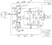
I tried a version of the original BH, with ecl82 (not for a special reason, I will try ecl86 in the future).
For some unexplainable reason I always try to do things a bit different, perhaps because I am rather curious

I put a LND150 mosfet on top of the triodes and used the mu-output to drive the pentode. I bypassed the top CCS with a 2meg resistor: forgot to draw that on the sketch. I read on the forum that this prevents "fighting" between the two ccs's.
Under the pentode I used the garter bias scheme as used by Shoog for his ecl82 headphoneamp.
I used a different feedback construction but perhaps it can be combined with the original (gingertube did this).
I have only a mono-version as a try-out.
Perhaps if someone wants to try this or a variation of it (LND150 cascoded ?/ 10M45S ?), it would be very interesting to hear if it sounds different/better than the original setup. I suppose you can also put the original Kimmel Mu-stage with a pentode on top at the front of the amp.
For some unexplainable reason I always try to do things a bit different, perhaps because I am rather curious
I put a LND150 mosfet on top of the triodes and used the mu-output to drive the pentode. I bypassed the top CCS with a 2meg resistor: forgot to draw that on the sketch. I read on the forum that this prevents "fighting" between the two ccs's.
Under the pentode I used the garter bias scheme as used by Shoog for his ecl82 headphoneamp.
I used a different feedback construction but perhaps it can be combined with the original (gingertube did this).
I have only a mono-version as a try-out.
Perhaps if someone wants to try this or a variation of it (LND150 cascoded ?/ 10M45S ?), it would be very interesting to hear if it sounds different/better than the original setup. I suppose you can also put the original Kimmel Mu-stage with a pentode on top at the front of the amp.
Attachments
- Home
- Amplifiers
- Tubes / Valves
- EL84 Amp - Baby Huey