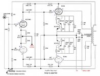
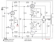
Dave, my attached schematic is the latest ECL86 amp referenced by Gingertube in his posting http://www.diyaudio.com/forums/showthread.php?postid=1078309#post1078309 on page 12 of this thread, so I presume it's the latest - just wanted to confirm this with Gingertube
Thanks
John
Thanks
John
Hi Jeff,
Most interested in your experiences with these rectifiers. Personally I cannot hear differences between them. I've used the "potato masher" 5R4's in several amps and like their ruggedness. Chose 5AR4 here for soft start and higher B+ yield.
Followup on your revelations only adds to my humiliation.
Although now wired correctly, fuses blow on switch-on, even 1.5A slo-blos.
Had this trouble in my SE211 amp, problem was arcing in an insufficiently insulated fil trans for the mercury vapour 866A rectifiers. Now there's a sight in operation plus smoothness even invisibility--getting way off thread, but remedy is the same--a new transformer....pic of 866's in action attached.
Anatoly:
I should have added re inputs close to 803S: if this amp didn't work out, I'd add another socket and try another very interesting PPEL84 amp--scary DC tho....
http://www.wdehaan.demon.nl/tubeamps/el84dc/index.html even more OT...
Apologies Gingertube!
Ken
Attachments
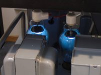
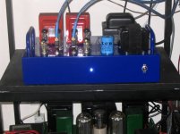
Bluey Baby Huey off at last.
Addendum.
In action at last.
Faulty Chian 5AR4 blew fuses. Replacement gave healthy 330V B+.
But: casual measurement of EL84 cathodes revealed one with a figure of 40V and rising 'til switch-off....aaarrrggghhh
What next!!
Replaced all sand on affected board to no avail. About to call on Ian for help, when had a flash of insight, and measured '84 grid voltage. Sure enough, one leaking green Russki coupling cap.
An RS replacement, and at last another reasonably well functioning amplifier, and a few less grey hairs.
Square waves OK, but there's some ?oscillatory patterns on one channel; pleased to show if anyone's interested.
Hard to determine power output,being only either 4 or 16 ohm output and measurement setup is for 8, and the RMS AC voltmeter awaits repair. Seems about a clean 7W,with not-so-clean 10W headroom.
The pic shows her feeding an ancient pair of Concertos, and sounding a bit rough to be frank,but is it the amp or the speaks??
Bass is terrific though, and sound very detailed,if top heavy.
In conclusion, thank you to Ian for his inspirational design, and the welcome help of others in this enterprise. Now for a much simpler PPEL34 amp.....
Attachments
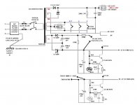
Hello gingertube and others. After reading through this thread I am curious if the attached scheme is correct. Also I would like to use a pre amp and wonder if I have this correct without the log. Sorry I am very new to this stuff, so trying to learn as I go. One question I have is where does the 0V at chassis ground #1 come from on the other channel? Any input would be greatly appreciated.
Thanks
Thanks
Attachments
dstockwell,
Schematics you posted look good except for:
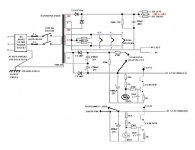
On the Power Supply sheet there seems to be a missing connection from the bases of the top CCS transistors to the junction of the 1K6 and 1K resistors.
The Hammond 1650E you list is 15W rated and MAY give better bass, however if you wish to save a few dollars the smaller Hammond 1608 would be OK.
On my current tweaked version of the EL84 Baby Huey I have:
1) A&R 4016 Vintage Oz potted Output Transformers (8K:4 ohms, 43% UL taps).
2) The 18K shunt feedback set resistor shown in your schematics is 33K.
3) There is no global feedback
4) The bypass capacitor network across each EL84 cathode currentsource is 1000uF/16V Blackgate with a parallel 1uF Polyphenylene Sulphide (PPS) cap.
5) The series resistors in the High Voltage feed I use are 4R7 2W but 47R will probably be OK. If the amp seems to lack some bass impact and slam try reducing this resistor - otherwise leave it at 47R.
On the earthing:
There MUST be a Chassis Earth #1 - Safety Ground close to the mains input socket and mains filter etc.
The will be a second chassis earth connection (for the 0V rail) preferrably near the ECC803 and toward the opposite end/corner of the chassis from the safety ground.
From this chassis connection a left and right channel 0V buss runs out and eventually join each other again at the main filter capacitor 0V connection. The earth wiring is in the form of connection along the 0V buss follows schematic - that is closest to the 0V chassis connection will be the shield of the cable which runs back to the isolated RCA input connectors, then the ECC803S grid resistor 0V side, then the cathode CCS 0V connection etc.
This Scheme keeps the high return currents such as the main filter cap charging currents at the far end of the 0V buss and away from the sensitive input circuitry.
Cheers,
Ian
Schematics you posted look good except for:
On the Power Supply sheet there seems to be a missing connection from the bases of the top CCS transistors to the junction of the 1K6 and 1K resistors.
The Hammond 1650E you list is 15W rated and MAY give better bass, however if you wish to save a few dollars the smaller Hammond 1608 would be OK.
On my current tweaked version of the EL84 Baby Huey I have:
1) A&R 4016 Vintage Oz potted Output Transformers (8K:4 ohms, 43% UL taps).
2) The 18K shunt feedback set resistor shown in your schematics is 33K.
3) There is no global feedback
4) The bypass capacitor network across each EL84 cathode currentsource is 1000uF/16V Blackgate with a parallel 1uF Polyphenylene Sulphide (PPS) cap.
5) The series resistors in the High Voltage feed I use are 4R7 2W but 47R will probably be OK. If the amp seems to lack some bass impact and slam try reducing this resistor - otherwise leave it at 47R.
On the earthing:
There MUST be a Chassis Earth #1 - Safety Ground close to the mains input socket and mains filter etc.
The will be a second chassis earth connection (for the 0V rail) preferrably near the ECC803 and toward the opposite end/corner of the chassis from the safety ground.
From this chassis connection a left and right channel 0V buss runs out and eventually join each other again at the main filter capacitor 0V connection. The earth wiring is in the form of connection along the 0V buss follows schematic - that is closest to the 0V chassis connection will be the shield of the cable which runs back to the isolated RCA input connectors, then the ECC803S grid resistor 0V side, then the cathode CCS 0V connection etc.
This Scheme keeps the high return currents such as the main filter cap charging currents at the far end of the 0V buss and away from the sensitive input circuitry.
Cheers,
Ian
Yes,
I would suggest that you remove that 12K global feedback resistor from the output transformer secondary. Leave everything else to that triode grid as is. You can always put the global feedback in latter if you feel you need it after listening.
The cathode bypass capacitor shown as 1000uF/16V - this value is just what I happened to have in my Blackgate capacitor box when I was experimenting. Either 470uF or 1000uF caps can be used BUT I would be happier if they had bigger voltage rating - say 25V rated minimum.
Higher voltage rating caps generally have lower ESR so - for example, if were using common electrolytics which can be bought from the local electronics store I would use 470uF/63V or 1000uF/63V
Watch the output tube dissipation. For a rail of 300V to 325V what is shown is fine. If the rail is 330v to 350V then change the 16 Ohm resistors in the "ring of two" current sources in each EL84 cathode to 18 Ohms to drop idle current from 38mA to 34mA
Cheers,
Ian
gingertube said:The cathode bypass capacitor shown as 1000uF/16V - this value is just what I happened to have in my Blackgate capacitor box when I was experimenting.
Hey Ian, thanks for all the help and inputs.
What about a 1000uf/35V ELNA Cerafine. Or go back to two caps and use ELNA Cerafine 470uf/63V. Their is a 1000uf 50V (FK Series) Blackgate on Partsconnexion, but that puppy is $25. Parts connexion also shows 470uF 50V but they are standard grade.
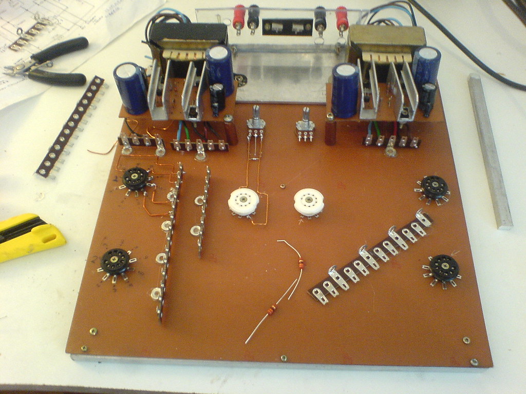
My first tube DIY
My english is terrible but i understand almost everything, so if i'm doing something wrong please tell me... thanks")
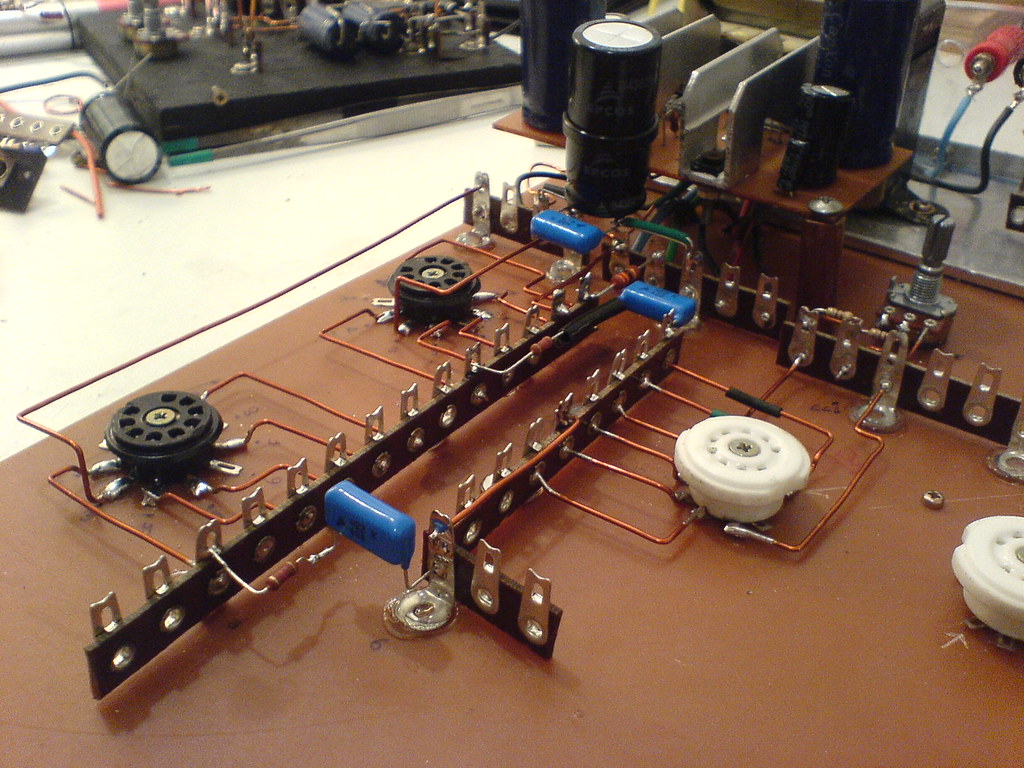
This is my first audio DIY, and i always want a tube amp to play my LPs... so i'm builting it hehe.
I'm an student of mechanical engeneering and eletronic is just a hobby (for now a big block its to big for my bench, but my dodge have a 318, the most popular v8 here in Brazil) so i'm opened to new suggestions
Under Construction:
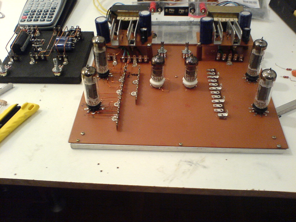
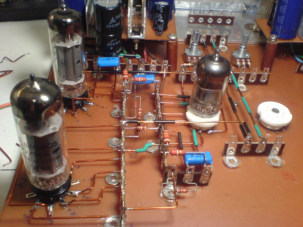
With the tubes:
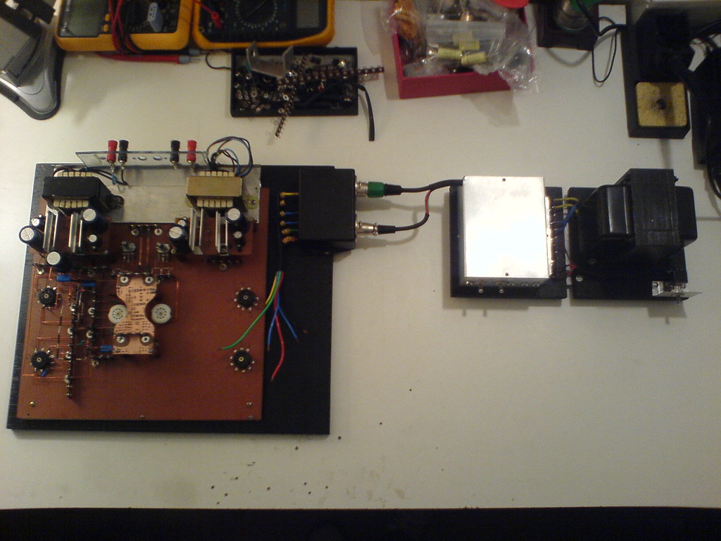
The left channel being constructed:
Done:
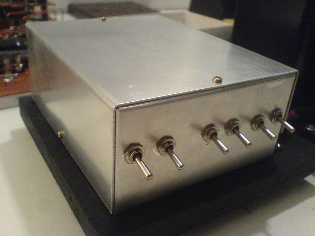
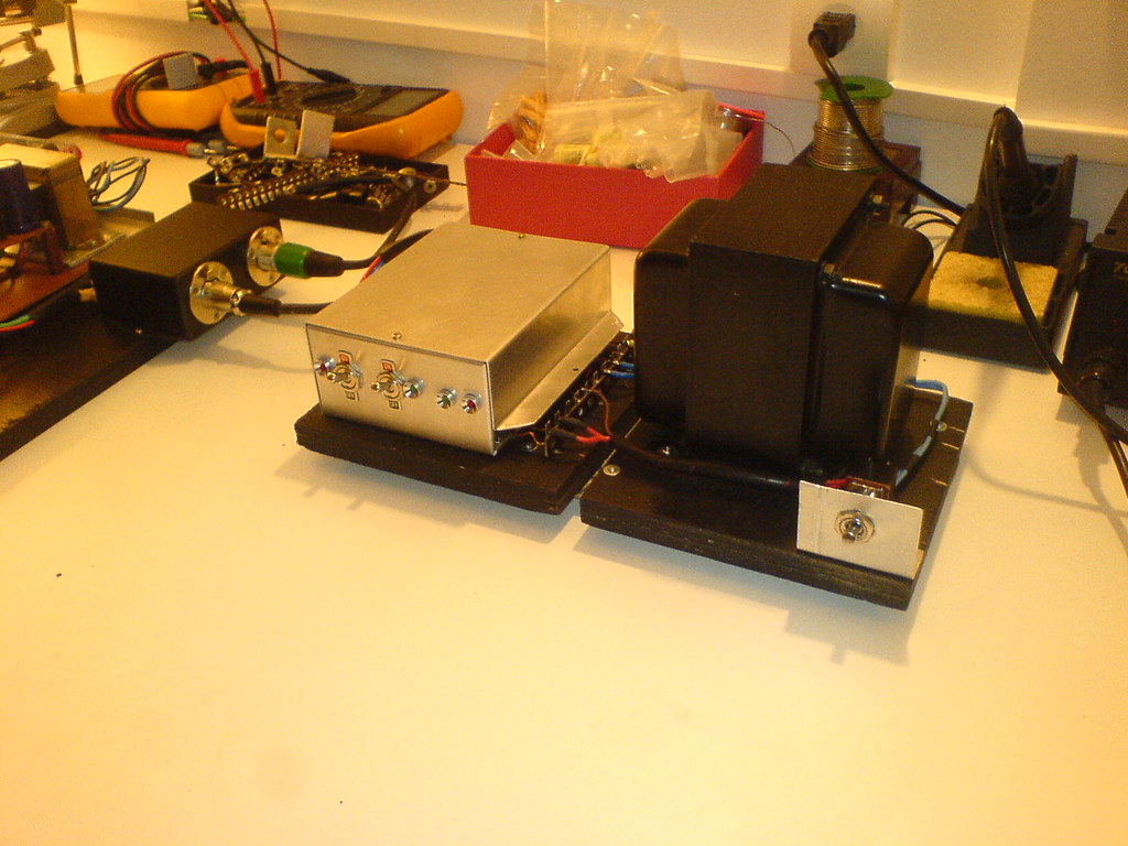
The PSU circuit box:
PSU:
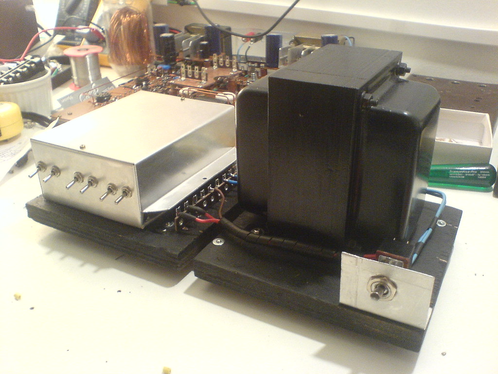
New setup:
Almost done:
. . . waiting for suggestions . . .
My english is terrible but i understand almost everything, so if i'm doing something wrong please tell me... thanks
This is my first audio DIY, and i always want a tube amp to play my LPs... so i'm builting it hehe.
I'm an student of mechanical engeneering and eletronic is just a hobby (for now a big block its to big for my bench, but my dodge have a 318, the most popular v8 here in Brazil
) so i'm opened to new suggestionsUnder Construction:
With the tubes:
The left channel being constructed:
Done:
The PSU circuit box:
PSU:
New setup:
Almost done:
. . . waiting for suggestions . . .
You have to be careful with all those right-angled wires. The electrons can get all confused and decorrelated after they skid around that corner at high speed. They can even fall out, making a big mess. At best, they end up all dizzy and bump into each other randomly. 
Seriously, that's very neat work and clearly took a lot of planning and preparation effort. Well done!
Seriously, that's very neat work and clearly took a lot of planning and preparation effort. Well done!
- Home
- Amplifiers
- Tubes / Valves
- EL84 Amp - Baby Huey