Hi, what power traffo are you using with that power supply?Hi.
Please find attached my configuration for the power supply. Will be more than happy to share the gerbers as well, but I would rather wrap up mine so that we're all sure everything is fine.
Cheers
Oh, forgot to mention that bit of info!Hi, what power traffo are you using with that power supply?
With this config I have used Hammond 369HX
Kind regards
Thank you for your kind words. The schematic is the one used in this thread. Also the PSU schematic is nothing fancy.Looks amazing! does this one use the original schematics from this thread? I see the schematics now. Please let us know if your test runs succeed. I think many people would like to build using your layout. If you don't mind that.
At a first test, it works just fine. I am waiting to have the chassis done and after I have it all in one piece, I will post the complete schematics I have used and the layouts.
TBH the reason why I have designed my own pcb was due to the fact that I wanted a compact one board assembly.
Will post any future updates.
 .. dB
.. dBOh! Sorry, didn’t get it from the first time. 🙂Just affirming that the amplifier is worthy of your effort as it has a wonderful sound")
To be honest, I went through all the posts on this thread and on the EL34 as well. A lot of usefull info.
@KDMAudio , I notice few things I like alot and some I suggested to apply on the EL34 version, not strictly needed here.
I report also some other comments.
The MJE340 on the powerdrive CCS to be able to run negative voltages below -100Vdc while having a reasonable margin on the needed +25V on the positive side, without going too close to the 140V limit of the 2N5550 or 160V of the 2N5551. How do you regulate the positive voltage for the powerdrive?
Fuseholders on PCB to simplify maintenance and installation.
1W resistors (if I see well) or higher.
The time delayed PSU is something I don't like, but I know it used alot.
I'd suggest you to apply pentode symbols on the pcb where the pentode noval are.
I don't see the two led mod on the phase splitter's CCS.
I don't see the 12AX7/6Н2П jumper.
There's no need to have huge 10 Ohm resistors on EL84 cathodes, as they dissipate 10-15 mW at idle and 150-200 mW peak.
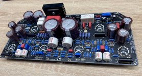
Signals from the phase splitter and from the output tubes seem to cross a big part of the pcb (coupling caps on bottom, output tube on foreground, one pentode on the back of the pcb. The other pentode in foreground, the output transformer connectors on the back of the pcb (around 650Vpp here).
I haven't seen the citation of the source of the idea for the schematic on the pcb.
It would be fair to add it, being something developed by members of the forum.
There could be more, but the image is hiding part of the pcb.
I report also some other comments.
The MJE340 on the powerdrive CCS to be able to run negative voltages below -100Vdc while having a reasonable margin on the needed +25V on the positive side, without going too close to the 140V limit of the 2N5550 or 160V of the 2N5551. How do you regulate the positive voltage for the powerdrive?
Fuseholders on PCB to simplify maintenance and installation.
1W resistors (if I see well) or higher.
The time delayed PSU is something I don't like, but I know it used alot.
I'd suggest you to apply pentode symbols on the pcb where the pentode noval are.
I don't see the two led mod on the phase splitter's CCS.
I don't see the 12AX7/6Н2П jumper.
There's no need to have huge 10 Ohm resistors on EL84 cathodes, as they dissipate 10-15 mW at idle and 150-200 mW peak.
Signals from the phase splitter and from the output tubes seem to cross a big part of the pcb (coupling caps on bottom, output tube on foreground, one pentode on the back of the pcb. The other pentode in foreground, the output transformer connectors on the back of the pcb (around 650Vpp here).
I haven't seen the citation of the source of the idea for the schematic on the pcb.
It would be fair to add it, being something developed by members of the forum.
There could be more, but the image is hiding part of the pcb.
The original design of the phase splitter supplied by the anodes of the output tubes belongs (to my knowledge) to Ives Monmagnon, with some more improvements (EG the powerdrive) by Gingertube, who gave also the name to the Baby Huey.
Other are minor improvements or variations on the original design, IMHO.
Other are minor improvements or variations on the original design, IMHO.
@zintolo
Hi! Thank you for your observations. In the following I will try to reply on some of them:
Regarding the VCE of the 2N5551 issue - I have asked myself the same question at some point, and the solution I came up with was using MPSA42 instead of 2N5551. Pinout is the same.
Both negative and positive voltages (fixed BIAS +CCS and Drive voltage) are obtained from the 50Vac tap of the power transformer. I won't argue if this is either indicated to do or not, but I have done it and works, so far.
The resistors are 1W rated - most of them , with some others being 2W rated. Also, because I wasn't sure about the cathode resistors of the pentodes, I decided to user 5W footprint on the PCB and Ohmite non inductive parts for assembly. I do understand your point but hence I will keep the PCB for myself I can live with that.
Thank you for the suggestion of using the pentode symbol on the silkscreen.
The CCS I have used on this version doesn't have 2 LED's. Maybe at some point I have missed that mod. Also, regarding the filament voltage jumper, it is not used because I didn't feel the need to have it on the PCB. I am using ECC's anyway.
The OPT are on the front of the PCB - they're facing the components side, and not towards the chassis. (or maybe I misunderstood your point)
Now, I know this is far from being a flawless PCB design, but as it is for me works fine. I do understand there will always be something to add/optimize/change according to different opinions of different people.
Quoting your observation "It would be fair" to add any citation of the source of the schematic, well.. it depends. I totally agree that if I make any profit with some PCB design then it would be really fair to give credits. As long as I have this PCB in my personal amp, for my personal use, with all the respect I don't find this a "must do".
I have stated in previous comments, thanks to the designer and to everyone's contribution to this project.
Cheers!
I love your design, please post final schematics and layout (Gerbers and BOM would be fantastic).Thank you for your kind words. The schematic is the one used in this thread. Also the PSU schematic is nothing fancy.
At a first test, it works just fine. I am waiting to have the chassis done and after I have it all in one piece, I will post the complete schematics I have used and the layouts.
TBH the reason why I have designed my own pcb was due to the fact that I wanted a compact one board assembly.
Will post any future updates.
Great project thanks!
I drew up this pcb to make it easier to convert an existing amp into a Baby Huey, I will likely get it made soon. The schematic is in the attached pdf (minus the 2 x 0.1uF coupling caps). I did draw up another pcb with the coupling caps on board as well. The resistors are standing up like in old guitar fx pedals. Any comments welcome, especially on the notes in the schematic attachment which was compiled from this thread.
Attachments
Last edited:
@Ian444
I suggest you the following to babyhuey (it's a verb) other EL84 based amps:
I still haven't tried, but another option instead of the cascoded CCS, for this simple application, can be a single BJT with higher Hfe and a Vce around 80, with a 7.2V zener instead of the led: an higher resistor multiplied by a single higher Hfe to have similar results with less components.
Or even the fet design used by Yves Monmagnon on the father of the Baby Huey: http://www.dissident-audio.com/PP_ECL86/Page.html
I suggest you the following to babyhuey (it's a verb) other EL84 based amps:
- include the PSU on the board, with generous space for radial caps;
- don't care too much on negative side filtering, as CCS will insulate from negative rail ripple;
- give the possibility to install a 7824 on the positive rail after the RC, as most of the amps will run in A1/AB1;
- add a resistor from the bias trimmers to ground to better focus the bias range and avoid to set the bias voltage too low;
- I've seen 500 Ohm balance trimmer works better IMHE with 12AX7 due to lower currents;
- Another 500 Ohm trimmer could be helpful to fine tune the bias of the phase splitter (jumperable if not needed);
- on the CCS, lower BJT will see a low Vce, so focus on maximum Hfe, upper BJT needs higher Vce (better if bigger enclosure to dissipate more watts);
- an higher current on the Power Drive can have a positive impact to the sound, especially when more swing is needed;
- I'd add to the pcb the differential feedback as well.
I still haven't tried, but another option instead of the cascoded CCS, for this simple application, can be a single BJT with higher Hfe and a Vce around 80, with a 7.2V zener instead of the led: an higher resistor multiplied by a single higher Hfe to have similar results with less components.
Or even the fet design used by Yves Monmagnon on the father of the Baby Huey: http://www.dissident-audio.com/PP_ECL86/Page.html
Your nickname suggests you are involved in build and sell audio equipments, that's why I proposed that.As long as I have this PCB in my personal amp, for my personal use, with all the respect I don't find this a "must do".
As long as it is for personal use, I totally agree with you.
- Home
- Amplifiers
- Tubes / Valves
- EL84 Amp - Baby Huey