Those specs are correct Lee.
Hi Bas,
Thanks very much, sorry to chase you. It’s a relief to get the right specs for the power supply to use with Prasi’s EL84 boards and power board.
Just waiting for them to be delivered.
Lee
Hi,
can two of these SMPS modules be a valid option to supply two monoblocks?
ZVS DC-DC 8-32V a +- 45V-390V step-up Modulo Alta Tensione Condensatore Carica Bordo | eBay
can two of these SMPS modules be a valid option to supply two monoblocks?
ZVS DC-DC 8-32V a +- 45V-390V step-up Modulo Alta Tensione Condensatore Carica Bordo | eBay
Code:
Output Voltage: +45~390V continuously adjustable (default output ±50V)
Output Current: 0.2A Max(with input, output pressure related,the higher the output voltage, output current is smaller)
Output Power: 40W (Peak 70W)
Working Temperature: -40 ~ + 85 degrees (ambient temperature is too high, please enhance heat dissipation)
Operating frequency: 75 KHz
Conversion efficiency: up to 88% (efficiency and input and output voltage, current, pressure-related)
Short circuit protection: Yes.
Over current protection: Yes. (Input current exceeds 4.5A, reducing the output voltage)
Over voltage protection: Yes. (Output voltage exceeds 410V, lowering the output voltage)
Input reverse polarity protection: Yes (non-self-healing, reverse burning fuse, try not reversed.)
Installation: Four 3 mm screws
Wiring: free welding output terminals
Size(L*W*H):60 x 50 x 20 mm
Last edited:
Thanks Francois, the main reason is not to be dependant on line supply for the working conditions of the amp, and at the same time find the best voltage for the amp with more accuracy. But I agree with you that it would be better suited for other projects where less voltages are needed, and maybe just the HV plus 12V for the heaters, so everything can be done with SMPS.
gingertube, Francois,
I would like to summarize the optimal transformers specs, because I haven't found all of them on this thread nor the wiki page. Please add and/or correct infos.
OT primary impedance:
8k will give more power and a bit more distortion;
10k will give less distortion, more class A range.
OT UL taps:
One option is to have no UL taps, but that implies to apply GNFB;
UL taps can be 20-23% as should be optimal for EL84, with no GNFB.
UL taps can be 43% as classic Hammond transformers, with no GNFB.
PT for two channels:
HV: around 0-250V (but the pcb I've receipt says 275V) 200 mA (it's 4x 30 ma = 120 mA plus peanuts for the PI, plus 50% margin when it goes into class B)
Heaters: 0-6,3V 5A (it's 4x 760mA plus 2x 600mA = 4,2 A with 20% safety margin)
Bias/PI/Powerdrive: 0-60V 200mA (because I need 3x the bias for powerdrive, but 50V are shown on the pcb)
PT for monoblocks:
HV: around 0-250V (but the pcb I've receipt says 275V) 100 mA (it's 2x 30 ma = 120 mA plus peanuts for the PI, plus 50% margin when it goes into class B)
Heaters: 0-6,3V 2,5A (it's 2x 760mA plus 1x 600mA = 2,1 A with 20% safety margin)
Bias/PI/Powerdrive: 0-60V 100mA (because I need 3x the bias for powerdrive, but 50V are shown on the pcb)
Choke (per channel, to substitute R27):
I've note a big experience in Hi-Fi, and my experience in instrument amplification is I would say opposite, so based on the opposite of my experience (choke and screen cap, in instrument amplification, are used to set the compression ratio/attack/release of the power amp) I would keep the resistance low as a primary goal.
Something like the specs of the Hammond 159S seem reasonable:
Inductance: 4 H
DC Current: 225 mA
Resistance: 65 Ohm
Max. DC: 500 V
Is there any suggestion on how to place the choke to avoid it to interact with PT/OT?
Thank you in advance
Roberto
Rotate the transformer 90 degrees to the adjacent transformer. In most cases, this is more than adequate and with layout, may not even be necessary.
Grounding scheme, heater wires, and layout all play a huge role. This is any easy one if you are building from a PCB.
I suggest you read Morgan Jone's book (if you haven't)
Cheers,
Greg
Grounding scheme, heater wires, and layout all play a huge role. This is any easy one if you are building from a PCB.
I suggest you read Morgan Jone's book (if you haven't)
Cheers,
Greg
Thanks Greg,
as for the PT/OT it is clear to me, I've built some guitar amps in the past, some with really close trafos, and the 90° plus headphone trick is something I know.
But guitar amps have more available space in layout, and choke often is mounted inside the chassis with no issues (even if I prefer it outside).
In this kind of amp, the layout is quite tight and I'm afraid of interactions between the choke and the trafos, that I would like to avoid.
Thanks Greg,
I've seen some layouts, and praxis is to apply 90° rule to choke too, and of course place it far from OT. So this way choke and OT have same orientation.
Other option, living in a 3D world, is to have a laydown PT and then apply the 90° rule between choke and OT.
Looking forward for the PT/OT/Choke values confirmation/suggestions from other users.
OT primary impedance:
8k will give more power and a bit more distortion;
10k will give less distortion, more class A range.
OT UL taps:
One option is to have no UL taps, but that implies to apply GNFB;
UL taps can be 20-23% as should be optimal for EL84, with no GNFB.
UL taps can be 43% as classic Hammond transformers, with no GNFB.
All this seems good to me.
PT for two channels:
HV: around 0-250V (but the pcb I've receipt says 275V) 200 mA (it's 4x 30 ma = 120 mA plus peanuts for the PI, plus 50% margin when it goes into class B)
Heaters: 0-6,3V 5A (it's 4x 760mA plus 2x 600mA = 4,2 A with 20% safety margin)
Bias/PI/Powerdrive: 0-60V 200mA (because I need 3x the bias for powerdrive, but 50V are shown on the pcb)
PT:Marc recommended a 230Vac PT for use with EL84’s which seems best to me too. I believe 200 ma is fine, however, I’m using 250 ma, because I like to wear a belt and suspenders

Heaters: 4.2 amps looks fine if you mean rectified current. Depending on how you are doing DC heating (if you do DC) you may want to increase the transformer current rating a bit to allow for losses in the rectification and regulation.
Bias: For EL84 about -15Vda bias is fine, so you need at least 2.5x or 3x (as you prefer) after rectification. Looks to me a 36VAC or higher transformer will work fine for bias supply.
Choke: Hammond 159S seems perfect, second to 159T.
Hope this sets your mind at ease. Good luck with your build.
Francois
Last edited:
Roberto,
I’m no expert in SMPS supplies; perhaps someone more knowledgeable would respond. But I think is is a clever solution and expect it should work well as you described. As designed the heaters on the EL84 PCB float (i.e. not grounded), so no issue with multiple grounds. Since the EL84s draw most current you could switch them around to achieve better balance if one PCB draws more than the other (if you have a matched quad). Perhaps you could wire the SMPS and PCBs together to see how it does before committing to this solution.
Good building and good luck!
Francois
Thank you very much for your prompt reply Francois, that 12,6V trick would allow to implement the other solution I was talking here: EL84 Amp - Baby Huey
And only the 0-50Vac 100mA would be needed, so a small 5VA toroid will make it easily.
And only the 0-50Vac 100mA would be needed, so a small 5VA toroid will make it easily.
Roberto,
Certainly helpful, thanks for posting these notes.
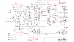
Regarding R3 and R4: Could you explain, please.
Vbias: EL84s are biased into cutoff (no current) at about -17V at the BH operating point, so perhaps the note that “EL84 is OK with -35V” is a mistake? I believe a small transformer with 36Vac and higher would be adequate to supply the bias voltage for the EL34s.
Cordali Saluti.
Certainly helpful, thanks for posting these notes.
Regarding R3 and R4: Could you explain, please.
Vbias: EL84s are biased into cutoff (no current) at about -17V at the BH operating point, so perhaps the note that “EL84 is OK with -35V” is a mistake? I believe a small transformer with 36Vac and higher would be adequate to supply the bias voltage for the EL34s.
Cordali Saluti.

Merci Francois, as you noted I'm very interested in this circuit, as the effect I noticed in applying it in another circuit has been very impressive.Roberto,
Certainly helpful, thanks for posting these notes.
Yes sure, this is an old rule of thumb used for triodes: 8/gm to set the grid stopper. In a typical new 12ax7 the gm is 1,6 mA/V, and this value goes down while the tube is getting old. Just to be on the safe side, I considered 70% of that value. Also in my guitar amps I use that value (or higher, if I want to cur highs with the benefit of Miller capacitance). It also would be better to have carbon comp resistors in these two points, because thay have the lowest inductance and lowest shunt capacitance, that is optimal for this purpose. Wire-wound are the worst.Regarding R3 and R4: Could you explain, please.
Pentodes usually follow an inverse proportionality too, but I'm not aware of a similar "golden rule".
No, it is not. It is not needed to bias the tubes (I agree -12Vdc are enough for them), but for Powerdrive. Powerdrive swings around three times the bias on the negative side, so it is needed to have the capability to have that voltage. I've simmed it and it is like that, and also other users on other forums, applying powerdrive on other circuits, have reported the same need of three times the bias on the negative side.perhaps the note that “EL84 is OK with -35V” is a mistake?
- Home
- Amplifiers
- Tubes / Valves
- EL84 Amp - Baby Huey