Ok, so I have the new 2n5551 on order as well as some new mosfets and led's.... could anyone upload a pic of the board with the proper pinout for the bjt's and fets so I can be sure I am installing them correctly??
That would be a great help! Other wise I am ready to re-assemble the amp as soon as the new parts arrive
I cant wait to finally here this thing sing!!!
That would be a great help! Other wise I am ready to re-assemble the amp as soon as the new parts arrive
I cant wait to finally here this thing sing!!!
Update: I have replaced the bc547 with the 2n5551 and I realized I had to take out D3 and D$ beacuse I am using a center tapped HV winding. My power transformer is not trying to melt itself anymore
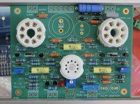
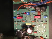
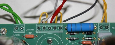
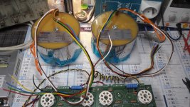
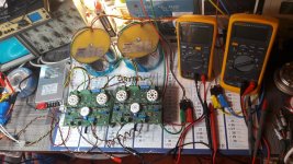
But, I am still having a problem with biasing. I have bias voltage available but turning the pots does not change anything...... I have attached some pics, any ideas??
But, I am still having a problem with biasing. I have bias voltage available but turning the pots does not change anything...... I have attached some pics, any ideas??
Attachments
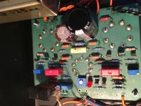
B+ is around 350v and everything else looks good, no more blinking led's...
I also have around 95v on the tabs of the mosfets. The negative voltage is however different on each output tube, and as I stated turning the pots does not change it....
I also have around 95v on the tabs of the mosfets. The negative voltage is however different on each output tube, and as I stated turning the pots does not change it....
Attachments
Grab some rubbing alcohol and an old toothbrush to clean up that flux off the board, It'll help prevent funky issues with leakage current down the line, and just plain look nicer
Have you tried measuring the resistance of the pots? I had some cheap trimpots that jumped track during adjustment and I really had to crank on them do get back on track.
Have you tried measuring the resistance of the pots? I had some cheap trimpots that jumped track during adjustment and I really had to crank on them do get back on track.
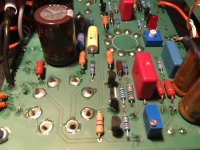
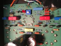
When you adjust the trimmer on the right side R41, you have to read the voltage from the test point TP1 on the left side and the reverse for the other channel, it was a layout mistake but finally it is easier not to have both hands on the same side
Please refer to the attached documents...
Rgds,
Marc
Please refer to the attached documents...
Rgds,
Marc
Attachments
Using EL34 Baby Huey with non UL output transformer
Hi,
I have bought long time ago two Amplimo 3A524 (2 x 2kohms 40 W) output transformer ( http://www.amplimo.nl/images/downloads/ds vdv/3a524.pdf ), at this time they didn't had the UL version, I have never used them
Finally, today I decided to test them on the EL34 Baby Huey wired in triode mode, this is very simple : you have just to connect the screen output of each tube to its plate output, you didn't need to add any resistor if you put on board the 270 ohms 2 W resistor as recommended.
It work perfectly, with a lower output power level of course but a very live sound, I still did not use the feedback input! Personally I prefer the UL version but I only tested one channel on a cheap loudspeaker and may be I have been too much satisfied with the version with the Hammond 1650N UL transformer
I will continue the test by connecting the second channel and after I will try to test the pentode mode, this is very simple again : I will connect the screen output to the high voltage (370 V) on the center of the output connector. Again this PCB is very flexible and can be used in many configurations... I would like to hear from those who have build it and hear their experience ?
Cheers,
Marc
Well I have finally had success!! It sounds great!! I am running pentode mode with EL34's and some old stancor iron. Very clean sound. One problem still though, I am not able to balance the 12AX7, one plate has 94v and the other 124.... Turning the pot does not change the voltages... Any ideas?
Using EL34 Baby Huey with non UL output transformer
Hi mctavish,
Nice to hear that your Baby Huey is singing and that you like the sound
For your 12AX7 balance problem, did you have the same situation on both channels ? If not it may be a problem with a tube or you will have to check if R7 and R8 are equal or if the trimmer is OK !
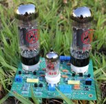
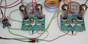
Following my previous post I made a picture of the stereo 6CA7 Baby Huey in triode mode with the Amplimo 3A524 toroidal output transformer, and it is playing while I write this message, I must say that I like it a lot now that both channels are connected
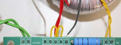
On the connector enlarged view you can see the two yellow straps and the transformer connection : the red one is the middle point where the high voltage is connected with the grey and the black ones which go to the plates of the output tubes.
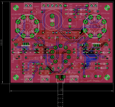
For those who have not yet build their amplifier I also add a modified layout of the PCB serigraph where the input connected to the GND are clearly indicated, this will help you to avoid the mistake of crossing the 50 V AC lines and make a short circuit on the power transformer
Marc
Hi mctavish,
Nice to hear that your Baby Huey is singing and that you like the sound
For your 12AX7 balance problem, did you have the same situation on both channels ? If not it may be a problem with a tube or you will have to check if R7 and R8 are equal or if the trimmer is OK !
Following my previous post I made a picture of the stereo 6CA7 Baby Huey in triode mode with the Amplimo 3A524 toroidal output transformer, and it is playing while I write this message, I must say that I like it a lot now that both channels are connected
On the connector enlarged view you can see the two yellow straps and the transformer connection : the red one is the middle point where the high voltage is connected with the grey and the black ones which go to the plates of the output tubes.
For those who have not yet build their amplifier I also add a modified layout of the PCB serigraph where the input connected to the GND are clearly indicated, this will help you to avoid the mistake of crossing the 50 V AC lines and make a short circuit on the power transformer
Marc
Attachments
After several hours of listening the stereo EL34 Baby Huey in triode mode I have connected the right channel in pentode mode (very easy I had just to remove the yellow jumpers from the screen to the plates and to connect them from the screen to the high voltage, the center connection of the output transformer with the red wires). I keep the left channel still in triode mode to hear the difference between them...
And I have been very surprised because the sound is very good in the pentode mode too, I have read a lot of articles where people said that triode output is much better than pentode output and frankly I didn't find a big difference between the two except that the pentode side seem more powerful, the music has more authority if I can say this way, but it is not very significant ! Of course I am not a golden ear man and I have no more 20 years since a long time but I can make the difference when I hear a good or a bad sound
I think the architecture of this amplifier is responsible for the good result whichever is the output connection, I forget to say that even in pentode mode, I still do not use any global feedback and the amplifier is very stable, no oscillation at all. I made some voltage measures that can be helpful for those who are building this amplifier and I also found that in pentode mode the bias was slightly higher than in triode mode (41 mA instead of 38 mA), the 6CA7 plates voltage is 350 V while the 12AX7 plates are at 170 V with less than 500 mV difference between the two triode
I am also testing a new DC/DC converter from China for the heater : Buy Products Online from China Wholesalers at Aliexpress.com which is running very cool with 7 A on 6.3 V but work best with more than 10 V DC on input (a 12 V 60 or 75 VA should be OK with a 35 A bridge and a 10'000 uF 25 V capacitor).
When I will have completed all these tests I will put the amplifier in a chassis with the Hammond transformers, but I may build an other one for these Amplimo toroidal output transformer
Reminder : for those who may be interested by this amplifier and missed the two GB, there is another one started by prasi on my request because I am too busy to manage it, and prasi made a good suggestion to made the PCB with 2.4 mm thick FR-4 (option 3)...
Rgds
Marc
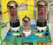
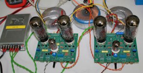
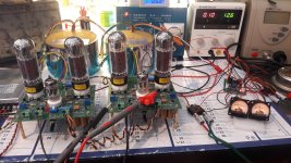
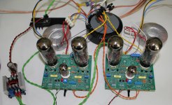
As we say in France : " One image tell you more than one thousand words !" ( "Une image dit plus que mille mots" ), I have made several pictures of the last setup. As you can see the left channel is still connected in triode while the right channel is in pentode, there is also a closer view of the pentode connection.
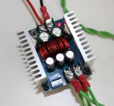
You can see on the third picture the DC/DC converter, it is announced for 300 W and 20 A which is probably over estimated, but it run very cool with 6.3 V 6.6 A for the heaters of the EL34 Baby Huey, it is a step down converter therefor you will need a higher voltage on the input, but the difference with a linear regulator is that it will not dissipate more, even if you put 20 V instead of 12 V on the input !
Bye,
Marc
Attachments
Hi,
Here are some news of my PCB EL34 PP.
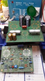
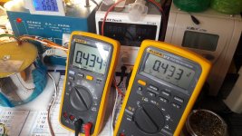
1st stage editing and first tests in my little lab. No smoke or bang, 4 bias is perfectly stable at 42mv after more than 4 hours of operation, the sound is perfect, no buzz no hum. The chemical caps are 500v 105 ° Nichicon
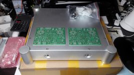
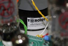
Small coquetry, coupling capas are Russian models MBM 0.1uF / 500v. The TS are the "Toroidy hooded". So far so good, no problem of components and the operation of the amp is perfect.  This is my first realization of a tube amp, I am very happy.
Now, I have to think about mechanics / integration. I kept this box, there will be work ....and .....
Great music to all,
Philippe
Here are some news of my PCB EL34 PP.
1st stage editing and first tests in my little lab. No smoke or bang, 4 bias is perfectly stable at 42mv after more than 4 hours of operation, the sound is perfect, no buzz no hum. The chemical caps are 500v 105 ° Nichicon
Small coquetry,
coupling capas are Russian models MBM 0.1uF / 500v. The TS are the "Toroidy hooded". So far so good, no problem of components and the operation of the amp is perfect. This is my first realization of a tube amp, I am very happy.Now, I have to think about mechanics / integration.
I kept this box, there will be work ....and .....Great music to all,
Philippe
Attachments


Hi Jorge, Hi All,
In your post 2024 you wrote :
" Changed the transistors to 2N5551 and now the led do not flash. I can adjust bias but to a certain level, can not go down to 30ma, the lowest level is around 61 or so ma. Is this of concern?
I have the bias set now to 61ma as is the closest value in the two channels that is steady. Maybe there is a bad tube due to overbias? It reached around 1.8Amps because the pots where in the high side, as soon as I turned down, the bias went down to a reasonable level. This lasted for a few minutes because I can not check both channels at the same time. "
I have now tested my EL34 Baby Huey (it is a 6CA7 Baby Huey in fact...) with the Toroidy 250 VA power transformer, it is a much more powerful beast than the Polytronik 141 VA custom version that I have used until now : it has two possible high voltage output of 275 & 330 V AC with a current of 400 mA compared to my transformer with 250 V AC with only 300 mA !
I am using the 275 V AC output since my board is populated with 400 v electrolytic capacitors and the 330 V AC will give too much DC voltage for them. I have now a voltage of 365 V DC on the 6CA7 plates and I have found that I cannot adjust the bias to less than 55 mA
After looking to the schematic, I found that the resistor R39 of 33 k between the negative power supply line and the bias trimmer make a voltage drop of nearly 30 V and therefor we have only about -23 V at the minimum value which does not give us enough margin to adjust the bias correctly ! I suggest to replace R39 with an 18k resistor or to put another 33k in parallel with the existing one (it will give 16.5 k) if you cannot remove the soldered one. I have done that and now I have -32 V DC on the trimmer and I can adjust the bias without any problem down to 10 mA (100 mV on the meter).
I use the 50 V AC output of the Toroidy transformer which is very convenient for this amplifier but while I was doing these tests I have seen that if this AC line is too close the the input wiring of the amplifier it can generate some 50 Hz hum, be careful in the layout of the signal input !
If you have any question don't hesitate to put them on the thread, I found improvement for this amplifier every time I work on it. I strongly recommend the Toroidy transformer, it is not too expensive and it has all the voltages needed for this amplifier. Beside that you can get it from TME ( TSTA 250/001 TOROIDY - Transformateur: toroidal audio | TME - Composants electroniques ) and they ship very quickly I ordered mine Saturday and received it today
You can also buy the nice SUPREME version produced on request ( SUPREME version is additionally shielded and potted in hand-made stainless steel box ) directly at Toroidy ( TSTA 0250/001 - Mains transformer for tubes - Shop Toroidy.pl ) but it is more expensive
Cheers,
Marc
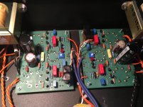
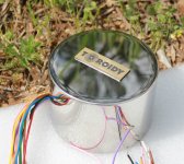
Another picture of the amplifier finished but not yet in the chassis 
I am quite happy with this new transformer, by the way I must say that I have no personal interest in the Toroidy Company, but their product really fit perfectly what we need for the EL34 Baby Huey, and also they are available with the nice look. I have used the two 6.3 V 7 A in serial to produce 17.5 V DC for a 35 A bridge which give me about 15 V DC on the input of the DC/DC converter for a nice regulated 6.3 V. I have also added two NTC resistor on the main input to protect the transformer during power up, I have used 10 ohms SG27
Unfortunately I have build my amplifier with 400 V capacitors, therefor I cannot use the 330 V AC output of the transformer, may be I will build a second one
Now I have also to finish the preamplifier and to start the new quad KT90 version
Cheers,
Attachments
- Home
- Amplifiers
- Tubes / Valves
- EL84 Amp - Baby Huey