Bonjour Sebastien,
I don't understand your question ? The bias is set with only one trimmer R41 which will define the current in V2 and we take the voltage on R43 on the cathode of V2 as a reference filtered by R64 and C14 to be compared to the voltage on V3, V4 and V5 cathodes to adjust the 4 tubes with the same bias. This circuit has been designed and simulated with LTSpice by Norman Koren : The Emperor's New Amplifier therefor I am quite confident that it should work correctly")
Thanks for your proposition, but I have already found the Audio Research VT130 schematic ( ARCDB - VT130 ) however it's a completely different design as there is only one cathode follower driving two output tube and the bias is not measured for each output tube...
For the heaters you are right with twisted pair when using 6.3 V AC, but I will be using 6.3 V DC supply, like in the EL34 Baby Huey, since it is very convenient and cheap to use small Chinese DC/DC switcher and that is the best solution to avoid all 50 or 60 Hz hum
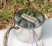
Indeed it's a nice project and may be the last one I will make with vacuum tubes, if like Norman Koren I am so satisfied with it that I will have no more interest to pursue the tube amplifier quest. By the way I have already bought the transformer from TOROIDY and they are really nice, see the photo of one of the 2k CFB output transformer...
It seem that I have some problems to load the photo of the transformer, therefor I will send it next time, sorry for that
Best regards,
Marc
I don't understand your question ? The bias is set with only one trimmer R41 which will define the current in V2 and we take the voltage on R43 on the cathode of V2 as a reference filtered by R64 and C14 to be compared to the voltage on V3, V4 and V5 cathodes to adjust the 4 tubes with the same bias. This circuit has been designed and simulated with LTSpice by Norman Koren : The Emperor's New Amplifier therefor I am quite confident that it should work correctly
Thanks for your proposition, but I have already found the Audio Research VT130 schematic ( ARCDB - VT130 ) however it's a completely different design as there is only one cathode follower driving two output tube and the bias is not measured for each output tube...
For the heaters you are right with twisted pair when using 6.3 V AC, but I will be using 6.3 V DC supply, like in the EL34 Baby Huey, since it is very convenient and cheap to use small Chinese DC/DC switcher and that is the best solution to avoid all 50 or 60 Hz hum
Indeed it's a nice project and may be the last one I will make with vacuum tubes, if like Norman Koren I am so satisfied with it that I will have no more interest to pursue the tube amplifier quest. By the way I have already bought the transformer from TOROIDY and they are really nice, see the photo of one of the 2k CFB output transformer...
It seem that I have some problems to load the photo of the transformer, therefor I will send it next time, sorry for that
Best regards,
Marc
Bonjour Marc,
Ok, I will do it in french and english.
In stand-by mode no problems but with a signal current on both side are in opposite phase. The op amp will try to have the same current in all tubes.
Au repose pas de pb, ca marche. Par contre avec un signal en entrée, le courant sur les étages de sortie est en opposition de phase. En présence d'un signal j'ai peur que l'AOP se batte contre l'étage splitter.
About heater, even in DC it's better to route as close as possible. PCB is less sensible to EMI and EMC. In your way of routing it made an induction loop.
But it's just my mind !
Best regards,
Sébastien
^ Man, those cans sure are pretty. too bad they don't ship to the US
Hello Gingertube et al,
I was thinking of trying to build one of these using the 6N2P and EL86 (or 6P43P-E) if possible. Would I need to change feedback resistors to the driver plates in this situation?
I have a bunch of 6P43P-E, 6P14P, and 6P6S, and so they would be a nice way to build up an amplifier for my father, and give him a supply of replacements to keep on hand. I'm leaning towards the EL86 with a lower supply voltage for the smidge higher power output, and because I have more of them
in post 1968 reaper996 says that shipping cost to USA for the TSTA 250/001 power transformer is only 10 US$...
In another post, the price for shipping in Australia is also very correct...
But don't forget that you may have to pay VAT and may be freight agent administrative cost
Rgds,
Marc
In another post, the price for shipping in Australia is also very correct...
But don't forget that you may have to pay VAT and may be freight agent administrative cost
Rgds,
Marc
Bonjour Sebastien,
Don't worry I understand very well English even if sometimes I didn't write very well
As you can see on Norman document and as I have written in my previous message, there is a low pass filter on the op amp inputs and a capacitor in the op amp feedback to eliminate the effect of the audio signal on the bias level, it work at very low frequency, it is a simple and élegant solution compared to some that are using a micro-controller !
Description from Norman Koren (with references of his schematic) :
"Bias servo and adjustment
The time-averaged (low pass filtered) dc current of an output tube operating in class AB fixed bias is relatively constant at low power levels but increases at high power levels. For this reason a fixed voltage cannot be used as a reference for biasing the output tubes. One tube (TU9, driven by TU5) operates at fixed bias, and its low pass filtered cathode voltage (CRF) is used as the reference for biasing the other tubes.
The bias servo is illustrated in the lower left of the schematic. It uses the LM324 quad op amp-- cheap but perfectly adequate. Inputs U1A, U1B and U1C of the LM324 compare cathode voltages 10C, 11C, and 12C with reference voltage CRF, which is the voltage on cathode 9C low pass filtered with RBS2 = 33k and CBS1 = 10uF ( located near U1B on the schematic). The LM324 outputs control the P-channel MOSFETs, each of which controls a voltage divider between VBB (-90V) and VOP (+12.5V) to deliver the appropriate bias voltage to the driver grid circuits (BIAS_6, BIAS_7, and BIAS_8). This measures between -45 and -50V in my amplifiers, which operate at 60 mA plate current. Audio purists please note: the servo operates at extremely low frequencies; the op amp and MOSFETs are well outside the audio signal path.
A single potentiometer, RB5 (in the VBB supply, bottom center), controls the bias current directly in TU9, and all the other tubes indirectly through the servo. Bias current may be measured across any of the 20 ohm resistors R9C-R12C as E/20. They should all be the same if the servo is working properly. 1 to 1.2 volts is a good nominal value, corresponding to 50 to 60 mA per tube (70 mA was used in the Dynaco Mark III). Increasing the current increases power consumption and reduces tube life and output power, but moves you closer to Class A (where both tubes always conduct)."
Best regards,
Marc
Quad EL34 Baby Huey / TENA Power Supply
Hello everybody,
Sebastien, your English is very good, at least for me
After the amplifier, I will add now the Power Supply part of the project, as you will see it is mainly based on the nice TENA description... I will use a 250 VA transformer also from TOROIDY which incule all needed voltages : https://sklep.toroidy.pl/en_US/p/TSTA-0250001-Mains-transformer-for-tubes/648
1) 275 V AC or 330 V AC @ 400 mA for the high voltage of 385 V DC or 462 V DC after rectifier (I will use the higher voltage of 460 V, with 60 mA bias x 4 = 240 mA plus the input tubes it should be OK)...
2) 50 V AC @ 100 mA for MOSFET drivers and bias voltage will give about plus & minus140 V DC after the doubler
3) two 6.3 V AC 7 A for heaters which will be connected to a bridge rectifier, a capacitor and a DC/DC switching power supply (may be I will put two connections on the amplifier PCB ?)
4) another 6.3 V AC 2A for the 12 V DC fot the timer (LM555) and for the op amp (LM323)
Of course this power supply will be for only one mono amplifier, anyway the weight of a stereo amplifier should have been excessive This is also probably why Norman Koren has build two mono blocs !
This Power Supply is not limited to the Quad EL34 Baby Huey / TENA amplifier, in fact it can be used with most tubes amplifier.
All your remarks, suggestions or comments will be appreciated, I hope to build this amplifier during the summer
Cheers,
Marc
Hello everybody,
Sebastien, your English is very good, at least for me
After the amplifier, I will add now the Power Supply part of the project, as you will see it is mainly based on the nice TENA description... I will use a 250 VA transformer also from TOROIDY which incule all needed voltages : https://sklep.toroidy.pl/en_US/p/TSTA-0250001-Mains-transformer-for-tubes/648
1) 275 V AC or 330 V AC @ 400 mA for the high voltage of 385 V DC or 462 V DC after rectifier (I will use the higher voltage of 460 V, with 60 mA bias x 4 = 240 mA plus the input tubes it should be OK)...
2) 50 V AC @ 100 mA for MOSFET drivers and bias voltage will give about plus & minus140 V DC after the doubler
3) two 6.3 V AC 7 A for heaters which will be connected to a bridge rectifier, a capacitor and a DC/DC switching power supply (may be I will put two connections on the amplifier PCB ?)
4) another 6.3 V AC 2A for the 12 V DC fot the timer (LM555) and for the op amp (LM323)
Of course this power supply will be for only one mono amplifier, anyway the weight of a stereo amplifier should have been excessive
This is also probably why Norman Koren has build two mono blocs !This Power Supply is not limited to the Quad EL34 Baby Huey / TENA amplifier, in fact it can be used with most tubes amplifier.
All your remarks, suggestions or comments will be appreciated, I hope to build this amplifier during the summer
Cheers,
Marc
Attachments
So, I am having some issues as well..... My build was coming along well. Everything is assembled and I have tested the heaters which are working fine. As soon as I apply HV the led's start flashing and the power transformer tries to fry itself! I am at a loss as to what to do next....
Any ideas as to what could be the issue? It is almost as if there is a short somewhere on the board.....
Help!!!
Any ideas as to what could be the issue? It is almost as if there is a short somewhere on the board.....
Help!!!
The blinking LED problem was the pin-out of the transistors, see post 2018
See also post 2010 about the wiring of the 50 V AC, even if it is AC it must be connected in the same direction on both boards because one of the input is tied to the ground...
Hope this will help you,
Cheers,
Marc
See also post 2010 about the wiring of the 50 V AC, even if it is AC it must be connected in the same direction on both boards because one of the input is tied to the ground...
Hope this will help you,
Cheers,
Marc
Flashing leds
Hi,
1.- Be careful with the 50 V bias AC supply. Although AC, one of the legs at the amp boards are tied to ground so you have to send the same lines from the transformer to the bias connector of each channel. The same cable from the transformer to both right screw and the other cable to both left screw of each amp board. If you wire it wrong, you are shorting to ground the power transformer. Hope you understand.....
2.- Do not use BC547 transistors. They are pin reversed and although being both PNP, the 547 C-E voltage is 45 V and the 2N5551 is 160 V. Another builder built the amp using BC547B with the correct pin order and worked but I imagine that those transistors would not last too much. I think he was going to change to the correct ones 2N5551.
3.- For the heaters is best to use a linear dc PSU, but, if you are going to use a smps, there is one in eflay that is rated 6.3 V and 10 amps for around 41$. I am using it. Take note that when you start the amp, as the filaments are cold, thus PSU does not start full steam, flashes it led until the heaters are warmed and start red. I first thought that there were a problem with mine....
4.- The electrolytic PSU caps of 400 V are IMHO very near their max value. If you are able, change those caps for 500 V changing the capacitance value so they can fit in the boards. I do not remember now correct values for 500 V, maybe Marc can chime in. In my case I could not change it because I ordered the same capacitance but 500 V and those caps do not fit, so I stayed with the 400 V ones.
5.- I also changed the polypropylene caps (3 per board) for 630v ones....
6.- Bias the output tubes correctly, around 50mA. In my case I can not go that low, mine are around 58mA. Less life tube. I can not tell why. This is beyond my electronics knowledge....Also remember that the bias pots are reversed, the left controls the right tube and the other way round.
7.- I have installed two chokes Hammond 159v instead of resistor. I am dealing now with some hum. For me, that resistor is low in ohms and in Watts ( but this is only an opinion based in experience not in knowledge)
YMMV...
Regards,
Jorge
Last edited:
Here is a small sale for folks in the US building this amp. Through tomorrow Antique Electronic Supply has 11% off of Hammond transformers plus free shipping. I have been watching for deals as I acquire the parts for this amp and the transformers are the most expensive parts.
No connection to this company, just a customer who saved some dollars.
No connection to this company, just a customer who saved some dollars.
So it looks like I was also unlucky and had the bc547 installed...... The bias transformer was installed correctly.
I have ordered the 2n5551 and am waiting for them to arrive. Should I replace the Mosfets as well?? What are the chances they are damaged? I also wanted to ask about the ppinout of the mosfets?
Thanks guys!
I have ordered the 2n5551 and am waiting for them to arrive. Should I replace the Mosfets as well?? What are the chances they are damaged? I also wanted to ask about the ppinout of the mosfets?
Thanks guys!
The BC547 is specified at Vceo = 45V max therefor it is not safe to use them in the driver stage even if some people have used them, beside that they must be soldered on the opposite direction of the serigraph ( see post 2018)...
I would recommend to use 2N5551 which have a Vceo = 160V max and have the US 2Nxxx pinout, not the European BCxxx one
Normally the MOSFET should be OK and the pinout is good, however if you mount them on the bottom side you have to turn them of course...
Rgds,
Marc
I would recommend to use 2N5551 which have a Vceo = 160V max and have the US 2Nxxx pinout, not the European BCxxx one
Normally the MOSFET should be OK and the pinout is good, however if you mount them on the bottom side you have to turn them of course...
Rgds,
Marc
Hi izozaya,
I wouldn't use those. They are Motorola numbers, a very old design and intended for TV vertical amplifiers. I use them in HV power supplies.
Their gain is pretty low and noise high compared to other transistors. They are intended for higher power operation than a signal transistor would be.
-Chris
I wouldn't use those. They are Motorola numbers, a very old design and intended for TV vertical amplifiers. I use them in HV power supplies.
Their gain is pretty low and noise high compared to other transistors. They are intended for higher power operation than a signal transistor would be.
-Chris
- Home
- Amplifiers
- Tubes / Valves
- EL84 Amp - Baby Huey