So...is suitable BC547B or not
Hi Marc,
I am confused...very confused...
Is it suitable the BC547B or not?
If I understand correctly what you are saying is not suitable.
But if I read correctly what Papavienneau has said (and used) it is suitable for the Baby Huey amp....
How can be explained that the amp built by Papavienneau is working with a non suitable transistor with Vce so different, 160V vs 45V?
In reference to the BOM "errors" I understand everything, it is normal. This is a really big effort from Marc and I appreciate what he has done as well as all the contributors to this thread. For sure I could not be able to design the PCB nor handle all the instructions and last but not least, the overhelming demand of PCB and all the work related. I can only say THANKS to Marc, Gingertube and all thread contributors. I will have a great amp soon thanks for them....
Regards,
Jorge
Updated BOM
Hi Jorge, Hi all,
You will find the new updated AND corrected BOM, again I am very sorry that there where some errors in the previous one, component values where EXACT but some supplier references were WRONG
To make it clear regarding the BC547B this transistor is functionally compatible with the 2N5551 BUT with a maximum voltage of only 45 V between collector and emitter (Vce) it is not enough in this design where bias and driver voltage can use power supply up to 100 V DC ! However it depend of your own bias voltage transformer (ie; 50 V AC will give you 65 to 70 V DC) and the tolerance of semiconductors is quite high therefor very often a 45 V transistor will survive in a 70 V circuit
Conclusion : it may work but it is not recommended, please use the 2N5551 as indicated in the enclosed updated BOM, and again sorry for the confusion, hopefully you helped us to correct these mistake and this will help others builders and me for the new version Quad EL34 Baby Huey that I am designing
Best regards,
Marc
Attachments
Hi Marc,
Please count me in the list for the PCBs for the Quad version of the Baby Huey amp....I hope the output transformers and also the power one of the EL34 version could be used in the new amp you are designing...
As I said in my previous message, you do not have to sorry for anything, this is DIY and I do not have to give anything for granted, I should have checked the pinout using the alternative reference...
Do you think that the bigger transistors, the STU9HN65M2 could be damaged due to the incorrect use and installation of the smaller ones, the BC547B?
Regards and thank you all (again)...
Jorge
It´s working now...more or less...
Hi,
Changed the transistors to 2N5551 and now the led do not flash. I can adjust bias but to a certain level, can not go down to 30ma, the lowest level is around 61 or so ma. Is this of concern?
I have the bias set now to 61ma as is the closest value in the two channels that is steady. Maybe there is a bad tube due to overbias? It reached around 1.8Amps because the pots where in the high side, as soon as I turned down, the bias went down to a reasonable level. This lasted for a few minutes because I can not check both channels at the same time.
I have some hum or noise but I feel is due to the cables that are not tide up. It is a birds nest. I have to check if the smps can go down to 6.3 volts and get rid of the two dc-dc convertors used for heating.
To be continued...
Regards,
Jorge
Hi Jorge,
I am happy to learn that your LED is no more blinking and that you can change the bias
For the bias 60 mA is on the high side but acceptable based on this datasheet : http://www.jj-electronic.com/images/stories/product/power_tubes/pdf/el34_e34l.pdf if both tubes are not biased at the same level, you will have more hum ! You can check the voltage on G1 it should be between -10 V and -15 V ? When you check the bias on the test point you are reading the voltage on the 10 ohms resistor, therefor you are reading 600 mV for 60 mA, if you cannot go lower either your negative supply is too small, it should be about -65 V or the resistor values in the voltage divider (R39 and R41 or R42) are wrong ? Be careful 1.8 A will kill the tubes
For the heater power supply I recommended this one : Bloc de Chauffage 6,3 V / 10 A Régulé pour Ampli à Tubes AL0007 : RADIOELEC : Composants et Modules Electroniques, spécialiste Audiophiles et Radioamateurs I have bought 3 of them that I use very often in my tubes projects... You can tell Alain that you buy it for my amplifier, he will know because several EL34 Baby Huey builders buy this switching power supply from him.
Good continuation,
Marc
Jorge,
Note that one trim-pot will decrease corresponding bias when turned counter-clockwise while the other will decrease its corresponding bias when turned clockwise.
Marc,
Love the boards. Played with one set for an hour or so using old 6V6 tubes and 10W output transformers borrowed from a Bruce Heran Mini Block project I am working on. Will replace BC547B transistors with 2N5551's when I get back to the Baby Huey. Thanks for the heads up.
Must first complete the Mini Blocks. May try to adapt one set of your EL34 boards to EL84 and see how the EL84 Baby Huey compares to Bruce's Mini Blocks. Providing you had spare EL84 boards for sale (or cared to share the files used to manufacture a set), a more elegant solution would be to go with proper boards and not mess the nice EL34 boards.
Regards,
Papavienneau
Hello papavienneau,
I am very pleased that you love the boards as you should have 8 of them if I am right
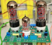
I have also tested the board with the 6V6 (see photos) and they sounded very nice too but I wanted to have more power, that was the purpose of the octal sockets after all The 6V6 are very close to the EL84 by the way, the EL84 are a little bit more agressive, not as sweet as the 6V6 and I don't see a real interest today to use an EL84 on this PCB, may be you can find an adapter ?
I have no more EL84 PCB in stock, and to speak frankly it is not designed as well as the EL34, you can see two mistakes on the photo (learning curve), hopefully someone on the forum see the error and inform me, too late to correct the PCB, but early enough to avoid sparks at the first power on
May be I could redesign it by changing the socket to noval on the EL34 version because this layout is much better, but currently I am more busy with the design of a tube preamp with remote control feature and a Quad Baby Huey with autobias !
Before to replace your BC547B you can check the voltage on their collector and emitter, if they survived until now you can leave them, unsoldering platted holes PCB is not very easy but for future board 2N5551 is safer...
Cheers,
Marc
I am very pleased that you love the boards as you should have 8 of them if I am right
I have also tested the board with the 6V6 (see photos) and they sounded very nice too but I wanted to have more power, that was the purpose of the octal sockets after all
The 6V6 are very close to the EL84 by the way, the EL84 are a little bit more agressive, not as sweet as the 6V6 and I don't see a real interest today to use an EL84 on this PCB, may be you can find an adapter ? I have no more EL84 PCB in stock, and to speak frankly it is not designed as well as the EL34, you can see two mistakes on the photo (learning curve), hopefully someone on the forum see the error and inform me, too late to correct the PCB, but early enough to avoid sparks at the first power on
May be I could redesign it by changing the socket to noval on the EL34 version because this layout is much better, but currently I am more busy with the design of a tube preamp with remote control feature and a Quad Baby Huey with autobias !
Before to replace your BC547B you can check the voltage on their collector and emitter, if they survived until now you can leave them, unsoldering platted holes PCB is not very easy
but for future board 2N5551 is safer...Cheers,
Marc
Attachments
-
 Ampli 6V6.JPG413.5 KB · Views: 662
 -
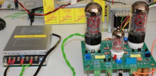 Ampli 6V6 avec transf R-TU101.JPG365 KB · Views: 622
 -
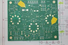 Error on EL84 PCB.JPG597.3 KB · Views: 640
 -
Schéma Preamplifier MK2.pdf110.4 KB · Views: 192
-
 PCB Preamplifier MK2.png43.2 KB · Views: 621
 -
Schema Input Relay.pdf115.5 KB · Views: 167
-
 PCB Input Relay.png81.3 KB · Views: 605
 -
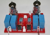 Photo Preamplificateur MK2 rear.JPG339.2 KB · Views: 284
 -
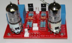 Photo Preamplificateur MK2.JPG380 KB · Views: 271
12AT7 ?
Hi,
My amp is singing beautifully... thanks to you all...
One thing I am in doubt.... can I substitute the 12AX7 for a 12AT7 ?
I have to much gain. I had to dial in the pots of the input to a safe level. The hum nearly went away although I still have the birds nest of cables....
Regards
Jorge
Hi,
My amp is singing beautifully... thanks to you all...
One thing I am in doubt.... can I substitute the 12AX7 for a 12AT7 ?
I have to much gain. I had to dial in the pots of the input to a safe level. The hum nearly went away although I still have the birds nest of cables....
Regards
Jorge
Last edited:
Hi Jorge,
You can change the 12AX7A for a 12AT7, but the characteristics are different and you will probably end up with higher distortion. This swap is popular with guitarists who actually do not want low distortion.
You can increase the feedback to lower the gain. This may cause you to recompensate the amplifier for stability. You would continue to use the 12AX7A
-Chris
Hum
Hi,
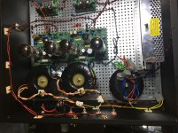
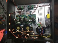
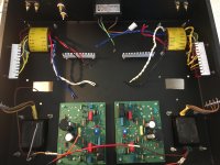
After a successful test, I installed the amp in the main system, with 92dB speakers, but the hum is quite noticeable. I tried to lower the gain with the input pots but it isn’t sufficient. I have connected the ground to only one point and I tried also to no connecting it at all. In both cases behave the same way.
The amp now is very tidy with al cables routed. See photos.
Any clue?
Jorge
Hi,
After a successful test, I installed the amp in the main system, with 92dB speakers, but the hum is quite noticeable. I tried to lower the gain with the input pots but it isn’t sufficient. I have connected the ground to only one point and I tried also to no connecting it at all. In both cases behave the same way.
The amp now is very tidy with al cables routed. See photos.
Any clue?
Jorge
Attachments
Last edited:
Ok. I will try
Hi Chris,
Thanks for your input. I’m waiting for a new power supply for the heaters, this will give some real estate to move down the amp boards because the little dc-dc power supplies at the bottom will be taken out. As soon as it arrives from France I will install it and make the movements required.
Regards,
Jorge
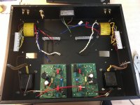
You do know that your circuit is really close to the transformers - right? Does the hum level drop if you move the PCBs away from the transformers? The power transformer at the very least.
-Chris
Hi Chris,
Thanks for your input. I’m waiting for a new power supply for the heaters, this will give some real estate to move down the amp boards because the little dc-dc power supplies at the bottom will be taken out. As soon as it arrives from France I will install it and make the movements required.
Regards,
Jorge
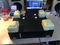
Progress! Should be finished by the weekend and then the testing phase...
But I am optimistic!
Outputs are from an AA-100 heathkit, ~7k to 4-8-16 ohm
Power trans are from Sony reel to reel , good quality shielded.
Two Hammond chokes and off we go!
But I am optimistic!
Outputs are from an AA-100 heathkit, ~7k to 4-8-16 ohm
Power trans are from Sony reel to reel , good quality shielded.
Two Hammond chokes and off we go!
Attachments

Hi,
For those who are still interested by EL34 Baby Huey PCB, there is a very good news on the GB forum : http://www.diyaudio.com/forums/group-buys/312869-gb-baby-huey-pcb-28.html#post5414734
Best regards,
Marc
For those who are still interested by EL34 Baby Huey PCB, there is a very good news on the GB forum : http://www.diyaudio.com/forums/group-buys/312869-gb-baby-huey-pcb-28.html#post5414734
Best regards,
Marc
New EL34 Baby Huey GB made by prasi
Hi,
May be my previous message was not clear enough
As I have explained that the second Group Buy that I have made was the last one because it was too much time consuming and that I prefer to use my time to make new project, but since there were still several requests for more PCB, I asked "prasi" if he would accept to take care of a new GB for the EL34 Baby Huey and he kindly accepted
Therefor, if you missed the two previous GB, you have now a new opportunity to get the boards from him and as you will see he had the good idea to offer the board in a thicker version of 2.4 mm which will be stronger to support power tubes
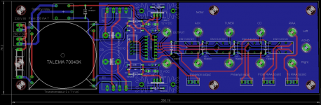
In the mean time, I have been working on a line preamplifier with remote control and on a new amplifier which is like the son of the Baby Huey and the TENA
As I have written in previous posts, I wanted to make a Quad EL84 to have more power than the original EL84 Baby Huey, but finally I found easier to just replace the noval output socket with an octal ones to use more powerful output tubes. That was the birth of the EL34 Baby Huey, that several people on this thread have built and like, as we know it... One of the problem for a quad EL84 was the number of MOSFET source drivers and bias trimmers, total = 8 !!! it was too complicated for a 20 W amplifier which was finally replaced by the EL34 BH, but I didn't forget this solution and since I have been very interested by the Norma Koren TENA amplifier The Emperor's New Amplifier since many years, I wanted to try to make some kind of "best of both world" version by using some of the most interesting features of each amplifier
From the Baby Huey I wanted to keep of course the shunt feedback, the differential input stage and the MOSFET bias/source drivers and from the TENA I wanted to keep the quad 6550 with cathode feedback, the second driver stage where the CFB is connected and the smart auto-bias concept... I hope the I am not building some kind of Frankenstein amplifier
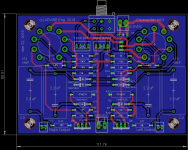
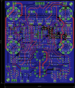
You can see the actual schematic (nota: R79 is not 100k but 4.7k) and PCB (a challenge for me) of this amplifier... I have already got some feedback from Ian (gingertube) to whom I have shown this before to publish it, and he gave me already some good advice that I added to the design, but there may still be some errors ? This is still a project in work but I will appreciate your comments or suggestions to improve it...
Best regards,
Marc
Hi,
May be my previous message was not clear enough
As I have explained that the second Group Buy that I have made was the last one because it was too much time consuming and that I prefer to use my time to make new project, but since there were still several requests for more PCB, I asked "prasi" if he would accept to take care of a new GB for the EL34 Baby Huey and he kindly accepted
Therefor, if you missed the two previous GB, you have now a new opportunity to get the boards from him and as you will see he had the good idea to offer the board in a thicker version of 2.4 mm which will be stronger to support power tubes
In the mean time, I have been working on a line preamplifier with remote control and on a new amplifier which is like the son of the Baby Huey and the TENA
As I have written in previous posts, I wanted to make a Quad EL84 to have more power than the original EL84 Baby Huey, but finally I found easier to just replace the noval output socket with an octal ones to use more powerful output tubes. That was the birth of the EL34 Baby Huey, that several people on this thread have built and like, as we know it... One of the problem for a quad EL84 was the number of MOSFET source drivers and bias trimmers, total = 8 !!! it was too complicated for a 20 W amplifier which was finally replaced by the EL34 BH, but I didn't forget this solution and since I have been very interested by the Norma Koren TENA amplifier The Emperor's New Amplifier since many years, I wanted to try to make some kind of "best of both world" version by using some of the most interesting features of each amplifier
From the Baby Huey I wanted to keep of course the shunt feedback, the differential input stage and the MOSFET bias/source drivers and from the TENA I wanted to keep the quad 6550 with cathode feedback, the second driver stage where the CFB is connected and the smart auto-bias concept... I hope the I am not building some kind of Frankenstein amplifier
You can see the actual schematic (nota: R79 is not 100k but 4.7k) and PCB (a challenge for me) of this amplifier... I have already got some feedback from Ian (gingertube) to whom I have shown this before to publish it, and he gave me already some good advice that I added to the design, but there may still be some errors ? This is still a project in work but I will appreciate your comments or suggestions to improve it...
Best regards,
Marc
Attachments
Dear Marc,
Are you sure of your auto-bias concept ? V2/V3 and V4/V5 are in opposite phase.
Audio Research used an auto-bias in VT130. I have schematics if you want.
About the PCB, a friend of me teach that it's better to route heater as close as possible. Like a twisted pair. In AC mode heater, it give best results.
Nice projects !
Regards,
Sébastien
- Home
- Amplifiers
- Tubes / Valves
- EL84 Amp - Baby Huey