6x4
I posted this in the power supply section but maybe this is a better place to ask...
I'm about to build a Aikido pre-amp and am planning to us a 6X4 rectifier in a LCRCRC psudo dual mono configuration. My PT has only one 6V heater output and will be used thoughout the whole pre-amp. My questions are:
1) Will this cause some hum issues due to having the rectifier and amp tubes sharing the same AC heater lines?
2) If I use all AC heaters, can I raise the heater bias on the 6X4 to about 70VDC?
3) If I rectifiy the heater AC , can I use DC on all the heaters including the 6X4?
The last resort would be to just aquire another TF to split off the rectifier from the rest of the amp but that requires another trip to the store. I'd like to use what I have in my junk box.
TIA..
Build it with what you have in the junk box. Listen to it for a while (weeks, or months) then go to the store. Buy an EI transformer for the heaters (not a toroid). Choose one with a dual chamber bobbin over one with a single. Power only the audio valve heaters from the new transformer.
Pay attention to heater to cathode voltage rating of 6X4! With heater positive wrt cathode, it is only 100V DC, or 200V DC+peak. As the voltage on rectifier cathode in choke input filter has a very large swing, running the shared heater could easily exceed safe specs, not to mention capacitively coupling 120Hz noise into signal circuits.
Guys, read the original post before sounding all reassuring, will you. He is running a choke input power supply. In case you never simulated those, I am attaching a plot of the rectifier cathode voltage in the choke input power supply with 275V DC output. The peak voltage on the cathode is nearly twice as much, and will exceed the 6X4 safety rating both ways (even if the heater is raised to 70VDC from the ground). You could be marginally within specs if the PSU output was lower, but doing so is not a good idea if you ask me. Run the rectifier heater from a separate winding, and make sure that winding has insulation that is rated for high voltage.
Attachments
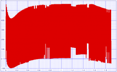
Oops, the attached plot was actually for a 310VDC output supply. Anyway, to repeat my point: the cathode voltage of choke input rectifier is not the same as DC output voltage of the power supply (as you guys are assuming if I read you correctly), but swings to a higher voltage (for ideal rectifier Pi/2*Vout, actually higher to accomodate filter losses).
Hi andrei,
I have never simulated a supply, so you have a good point. A 10uF cap and lower voltage transformer would then solve this issue.
I see many older preamps and tuners using this tube with 300 V ish supplies, therefore I was not too concerned initially.
Thanks for bringing this up.
-Chris
I have never simulated a supply, so you have a good point. A 10uF cap and lower voltage transformer would then solve this issue.
I see many older preamps and tuners using this tube with 300 V ish supplies, therefore I was not too concerned initially.
Thanks for bringing this up.
-Chris
In reality, I sort of lied about my line up. You might want to call CLCRCRC but the first cap is usually less then 5uF. I usually use that first cap position to tune in my deisred B+ output voltage. The idea came from Gordon Rankins 45 Bugle amp.
http://www.wavelengthaudio.com/bugle.pdf#search='rankin%20bugle%20amp'
So is the Bugle a choke or cap input power supply?
http://www.wavelengthaudio.com/bugle.pdf#search='rankin%20bugle%20amp'
So is the Bugle a choke or cap input power supply?
In the original article that accompanied the Bugle schematic, Gordon refers to the power supply as "choke input". He goes on to state that the small cap Cx is use to fine tune the output voltage. he used a .68uF cap which does not really change the choke input characteristics. A 5uF cap will make the design look a lot like a cap input filter, depending on the load current.
anatech said:I have never simulated a supply,-Chris
http://www.duncanamps.com/psud2/
It's free, it's easy, it works.
Sheldon
- Status
- This old topic is closed. If you want to reopen this topic, contact a moderator using the "Report Post" button.