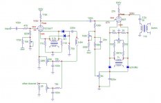
I just finished putting together and doing initial testing on a stereo 801a SE amp. It's resistor loaded with a parafeed type output. I got the original design from Steve Bench's site: http://members.aol.com/sbench/inp_dri.html
Also linked there are discussions on hum cancelling methods and starved filaments, both of which I used. By fiddling with the components, I was able to get to about 0.5mV on the outputs. I suspect that with an oscilloscope, one could do a little better.
I made significant changes in only two areas. I used a 0.9H choke (cause that's what I had readily available) instead of 4.5H, and so I adjusted the associated cap to 220n from 47n.
The other change was to the value of the bypass cap in the cancellation circuit for the 801 grid. Instead of 2.2u, I found that about 20-40n worked best. I did this by voltage measurent and ear, and could get significantly lower than with the spec.'d cap. I don't know why the value should be so different.
A further note on the schematic I used: I had only one 7v filament supply, so there are two compensation circuits, though not shown that way below, that are both run off the same supply. I know this is not ideal and gives me very limited differentiation for the standard hum bucking pot. It works ok with one well matched set of tubes I have. I will eventually replace the transformer or add an additional 7v supply so that I have completely independent circuits.
Any comments/ suggestion would be most welcome. I am particularly interested in comments on the power supply. It models well for static conditions with about 3mV ripple for B+ and a fraction of a mV for the driver. But I wonder if the impedence of the driver side might be too high. One mitigating factor is that I'm only using these amps to produce the spectrum above about 300hz.
Attachments
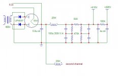

EC8010 said:I think you want to correct your diodes in that bias rectifier drawing. If they were really connected that way they'd be short-circuiting the transformer!
Oops. I get dizzy after a while using Microcap to draw the circuits.
Attachments
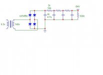
kevinkr said:I am assuming that your rectifier is not really a 6X4 - this is definitely not a good choice at the voltages shown.
Kevin
Thanks for the reply. Ok, sow why is that? And I'm not being argumentative. I'll freely admit my ignorance. I looked at the data sheet for the following.
Heater negative with respect to cathode: 450 Volts
Positive ditto: 100 Volts
PIV: 1250V
Current: 210 mA
Transient peak current: 1A
So in looking at those values, my reasoning was that the heater is floating, so I should be ok. The max. swing with the bridge is a little over 600 volts.
PIV is about 650.
Current is only about 25 ma
Transient peak current only exceeds 1A (about 1.2)for a couple of cycles. With PSUD that assumes the diode is hot on turn on, so I would guess with normal warm up that the peak is less than 1A?
So where did I go wrong? Hasn't blown up or acted funny -- yet.
Sheldon
noise
So, whaddya think. How should I proceed to refine this? I'm not opposed to sand or DC on the filaments, but I'd like to see what I can squeeze out of this cancellation method. If nothing else, cause it's fun and I learn a lot doing it. May have to get a scope though.
Sheldon
So, whaddya think. How should I proceed to refine this? I'm not opposed to sand or DC on the filaments, but I'd like to see what I can squeeze out of this cancellation method. If nothing else, cause it's fun and I learn a lot doing it. May have to get a scope though.
Sheldon
Attachments
Hi Sheldon,
I did take a look at the 6X4 specs this morning, my belief is that you are running the tube relatively near to the maximum ratings, but appear to be inside of it with the possible exception of the transient peak current at warm up. If you exceed the peak transient current spec during warm up the rectifier may arc and possibly destroy itself in the process.
I will admit I have a personal bias against the 6X4 in anything but very low voltage, low current applications, and have had some arcing problems with them even when operated conservatively. I also believe perhaps erroneously that the small envelope, and cathode size at this level of electrical performance results in a relatively short service life except in low current, low voltage applications.
I would be very worried however about having 650V on the pins of any common 7 pin socket I am familiar with - clearances are pretty marginal at this voltage, although obviously according to the specification it can be done.. FWIW I can't recall having seen a commercial application where one of these rectifiers was used in an application requiring much more than 30mA at 250V..
Because of the voltages involved I would recommend a 6CA4 in this topology or better still a 5AR4..
Thanks Kevin,
I'm not at low voltage/low current. But I am at very low current, so maybe I can get away with the higher voltage. We'll see. I have a few and if I have problems, I'll switch to a 6CA4, since that's a noval.
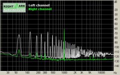
Below, I've posted the noise spectrum without the compensation circuits. The 120hz band is of course higher, but the comp. circuits (at least as I have them) appear to introduce some higher frequency harmonics (see above). Any thoughts anyone on the lesser evil?
I would guess that I could do a better job of reducing the 120 without adding the other noise, but that would mean a scope and some time. I'll have to think about that one.
Otherwise any thoughts on the power supply generally and where I can reduce noise easiest? I don't want to start chasing my tail if I can help it. Mind you, I have to be within inches of the speaker to hear noise with no input. But I don't know how it with intermodulate with music. My thinking is that the lower frequency components should be less of a problem. This is especially true in my case, since the horn response drops fast after about 300hz. But again, I don't know how things will combine with music.
I'm not at low voltage/low current. But I am at very low current, so maybe I can get away with the higher voltage. We'll see. I have a few and if I have problems, I'll switch to a 6CA4, since that's a noval.
Below, I've posted the noise spectrum without the compensation circuits. The 120hz band is of course higher, but the comp. circuits (at least as I have them) appear to introduce some higher frequency harmonics (see above). Any thoughts anyone on the lesser evil?
I would guess that I could do a better job of reducing the 120 without adding the other noise, but that would mean a scope and some time. I'll have to think about that one.
Otherwise any thoughts on the power supply generally and where I can reduce noise easiest? I don't want to start chasing my tail if I can help it. Mind you, I have to be within inches of the speaker to hear noise with no input. But I don't know how it with intermodulate with music. My thinking is that the lower frequency components should be less of a problem. This is especially true in my case, since the horn response drops fast after about 300hz. But again, I don't know how things will combine with music.
Attachments
Hi Sheldon,
For whatever reason I am unable to open the attachment you included with your message, apparently my png viewer doesn't like your file format..
In general harmonics in the 120Hz to 180Hz range are much more annoying than at 60Hz as the ear can be up to 20dB more sensitive at these frequencies. You indicate that the speaker system driven by this amplifier has a cut off at 300Hz, depending on how steep the slope is some noise below this can be tolerated.
If you are concerned about IMD products I would run a simple test at even say 1kHz at something like 10dB down from full power and see where and how much IMD you have - if it is 60dB or more down from your 1kHz tone it is probably not much of an issue, much higher than this and I would be concerned to the extent that I would devise an experiment to determine whether it was audible or not. Significant tones could be found at 820Hz (180Hz), 880Hz (120Hz), 940Hz (60Hz) and 1060Hz, 1120Hz, and 1180Hz, plus possibly intermod of the 2nd harmonic as well.. Note that the root of the sum the squares of all of these tones should be no more than -40dB (1%) and hopefully better than this.
Note that as you approach full power these products may become quite visible, and this is acceptable if at "normal power levels" (say 10 to 20dB lower) the residual IMD is acceptable.
Finally despite the above comments if it sounds good to you and is acceptably noisy at the listening position I would not obsess over this issue.
Kevin

Thanks for the reply Kevin. I'll play some more. It actually sounds pretty nice on limited listening so far. Without the compensation circuit, I get about 6mV mostly 120hz hum. Can't hear it more than a couple of feet from the horn. As for the images; hmmm, I can open them with my pc but they won't open on the mac. Let me see if I can save them as something else and post.
Sheldon
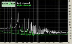
Here's with the cancellation circuit (saved as a jpeg, prior it was a png)
Sheldon
Here's with the cancellation circuit (saved as a jpeg, prior it was a png)
Attachments
Hi Sheldon,
I was able to take a look at the spectra posted - I am wondering about the differences between the left and right channels in the two graphs.
Can you elaborate, perhaps I need to reread the rest of the thread..
I will say that such a complex and rich spectra on the left channel is a disturbing thing to see. What exactly are we looking at when we look at the two spectra shown? If this is real I would say this hum cancelling circuit is a non contender..
On the non cancelled one I see a peak at -40dBv which is equivalent to 10mVrms unless you are in peak detection mode rather than rms mode, this is quite a lot of 120Hz buzz. (hum at 60Hz, buzz is 120Hz, 180Hz, 240Hz)
I would consider -70dBv as acceptable at 120Hz.
Umm if you can hear it several feet away from the speaker this is definitely too much noise, and it will modulate the quiet passages in any music you are listening to..
Sorry Kevin for the somewhat inept presentation. The green trace is the loop back into the sound card from the sound card output. The white trace is the amp output.
Maybe I was a little too liberal with my description of the speaker level noise. I can hear it about a foot or two away (it's a horn), but not much further. Still, maybe DC in my future? I don't have the tools to really chase down the cancelling method. Any comments on the general design of the power supply or recommendations?
Thanks Again,
Sheldon
edit: For completeness, I should note that my listening position is about 15' from the speakers. They are about 105db or a little more. The horn rolloff is approximately 2nd order at around 300hz.
Hi Sheldon,
Thanks for the clarification, it does help considerably!
I think in terms of a horn running above 300Hz that there should be no audible hum at all at any distance.. (Ouch!)
A bigger concern is all of that spectra extending from near dc to light, when you do a root square summation that is one heck of a lot of noise even though individually they are pretty far down.
I think it would be better to use constant current dc to heat the filaments and use some additional chokes in the filament lines for improved high frequency isolation from the supply if that concerns you. (I no longer use the chokes as it doesn't seem necessary in my electrical environment.) Linear Tech makes some wonderful ldo's that are perfect for use as constant current regulators. Take a look at the LT1083, LT1084, and LT1085 series. You would need one for each DHT with a separate filament winding, bridge rectifier and a couple of electrolytic caps, plus a couple of resistors - very simple. Current can be made adjustable if needed..
It should be possible to reduce the noise down to less than 0.5mVrms broadband with a very simple regulator, good layout and some shielding if necessary. This should result in virtually no audible noise at the speaker.
Some other thoughts about the filament supplies. All of that hum cancelling circuitry is more complicated than a simple dc filament supply for the 801's.. AC heating without any finagles should be fine for the 6SN7, just tightly twist the filament wires, make sure that there are no "loops" around the socket and if there is a center tap either ground it or elevate it maybe +20V above ground with a resistive divider, and bypass same with a moderately sized el. cap.. 1mA ought to be enough current in the divider so you might try 20K and a 280K resistor in series, with bypassing by 22uF/35V cap to ground. Should there be no center tap a pair of 100 ohm resistors in series across the filament transformer will accomplish the same goal as a connection point for the divider or ground connection.
Kevin
Edit: Added some other thoughts..
- Status
- This old topic is closed. If you want to reopen this topic, contact a moderator using the "Report Post" button.
- Home
- Amplifiers
- Tubes / Valves
- 801 low power SE amp