Hi Tubesin,
Just checked, sorry I don't have it.
One tube went bang? Probably a tube fault or I'd expect more to go. AR likes to regulate the screens, so check that. One reg does both channels I think. You may have lost a resistor or two, so check them. There is always the bias supply to look at also.
What brand of outputs were you using?
-Chris
Hi Tubesin,
Now there is a sure sign of excessive current. A blown resistor may be arcing and you really have a blanket problem affecting all those tubes.
The guys at AR are pretty decent. Try sending them an email requesting a schematic. Let them know what you have found.
-Chris
Now there is a sure sign of excessive current. A blown resistor may be arcing and you really have a blanket problem affecting all those tubes.
The guys at AR are pretty decent. Try sending them an email requesting a schematic. Let them know what you have found.
-Chris
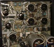
Yes, I'll do it. I suspect the power tubes are not strong enough, or, wearing out is the cause. I'll replace the resistor and a fresh set of tubes to see. Since all others resistors to the tubes look according to the values on the respectives colors, or, maybe, some over loaded and maybe weak or noisy or arcing when power on. Yeah, its very nervous. Also, there is a tube regulated supply in the middle of the chassis, it supplies to the voltage and driving tubes of both channels it looks. Does the big power supply capacitors harmed with the failing tubes? I attach a pic, the resistor at the same level of V15 and V13 are open to ground.
Attachments
Hi Tubesin,
That regulated supply is most likely for all the screen grids, both channels. The caps will be fine, age effects excluded.
I strongly recommend that you obtain a schematic from the manufacturer. I do have other schematics in electronic format if it will help you.
Do not just install a new set of tubes and "spark" it up. If you yank the outputs you can run the amp up to about 90 VAC. Watch for smoke (you shouldn't get any, but we are dealing with a failure). Now you can take measurements to check grid bias voltage and screen voltage. You can bring the AC voltage higher to make the plate voltage agree with normal values, the heater voltage will be slightly low.
-Chris
Hi Chris,
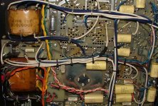
The screen regulation circuit board is in between opt and power transformer. For screen regulation, I think does not need to use KT88 as a pass-tube. I'm still thinking how to reactivate the amp and the use of a variac is a must. But I don't know if the relay in the lower part wl activate or not if I inject 100volt to the primary(the unit is 220V). I attach a photo of the underside for your appreciation
The screen regulation circuit board is in between opt and power transformer. For screen regulation, I think does not need to use KT88 as a pass-tube. I'm still thinking how to reactivate the amp and the use of a variac is a must. But I don't know if the relay in the lower part wl activate or not if I inject 100volt to the primary(the unit is 220V). I attach a photo of the underside for your appreciation
Attachments
Hi Tubesin,
Sorry, I thought you were 115V over there. Run up to about 180 VAC in that case. If they used a KT88, continue to do so. I see they did use a 6550A in the D90. Some of these amps will be close to the one you are working on.
How many output tubes per channel did you say it was using?
-Chris
Sorry, I thought you were 115V over there. Run up to about 180 VAC in that case. If they used a KT88, continue to do so. I see they did use a 6550A in the D90. Some of these amps will be close to the one you are working on.
How many output tubes per channel did you say it was using?
-Chris


Originally posted by: Tubesin
Up to now, I discovered one side of theparalell tubes cathode to ground resistors of 1 ohm? are open.
From looking at the 1st pic you posted and from this site
www.vintageampdoctor.co.uk/audio_research_d115.htm
your cathode to ground resistor should be .1 ohm (1/10).
Brown = 1
Black = 0
Gold = *.01
Gold = 5%
__________
0.10 ohms
Can't quite make out last (5th) band which is tempco, IIRC.
Cheers
Wayne
- Status
- This old topic is closed. If you want to reopen this topic, contact a moderator using the "Report Post" button.
- Home
- Amplifiers
- Tubes / Valves
- Schematic