Forgot to say this is my first big amp project, I only did headphone and guitar before. I think and hope the next one WILL look better!
Ohh....good to know...
I'm sure next one will look better......isnt'it?
")
Ohh....good to know...
I'm sure next one will look better......isnt'it?
Whoa... hold your horses!
No need to be sarcastic, I'm sure Tony can defend his aesthetic choices without your help, if he so pleases.And yes, I always try to improve the looks of my builds.
I feel much shame to publish any photo in this forum since the quality control of some members is exquisite. Sorry for participate in this forum with my trash.
Hi Dady
Nice to see you around here.
Can you put a link to your audio work ?
I was without phone the last three month, in the stone age, surely I missed something.
I feel much shame to publish any photo in this forum since the quality control of some members is exquisite. Sorry for participate in this forum with my trash.
Oh, come on.
Here, this was my first headphone amp. Made it in a sugar box. Re-wound the toroid myself, by hand (took me ages). Nice, eh?
Attachments
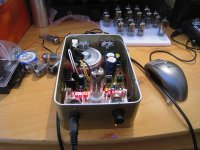
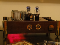
Sure. Here is the GM-70 SE amp that I've just (almost) finished.
My own schematic, but it's nothing really special.
It outputs a measured 29W RMS before distortion shows. The first stage is a CCS loaded, LED biased D3a (the photos were taken with an E186F in that position). The D3a has enough swing to drive the GM70 into clipping.
The GM-70 are fixed bias. They are constantly monitored by an Arduino microcontroller that I've programmed, which switches off the amp in case of problems. It also does soft start and temporisation, plus LED control to indicate status, problems or overload/clipping.
OPTs are custom gapped (90mA) Lundahl LL1688.
The supplies are in a separated chassis. There are no filtering chokes in my supplies - it's done with Mosfets and SiC Schottky rectifiers, including the 1050v GM70 supply. The kilovolt supply is not stabilized, only filtered;
the 350v supply is stabilized, not regulated (I do not like the sound of regulated supplies).
Together with Rod Coleman's filament supplies, this makes the amplifier absolutely silent, ear to the (95dB) speaker.
It sounds great.
I forgot to mention that Tony built his own enclosures, do you too ?
http://www.diyaudio.com/forums/tubes-valves/216206-my-russian-set.html
BTW. You should to drill the holes as well as he does.
Attachments
I forgot to mention that Tony built his own enclosures, do you too ?
http://www.diyaudio.com/forums/tubes-valves/216206-my-russian-set.html
BTW. You should to drill the holes as well as he does.
Yes. I know the thread and I admired the quality of that chassis. I didn't like the apparent electrolytics, but it's a nice project anyway.
These holes look so good because he powder coated the chassis *after* he drilled. I didn't. Maybe on my next project? Thanks for the suggestion.

I forgot to mention that Tony built his own enclosures, do you too ?
http://www.diyaudio.com/forums/tubes-valves/216206-my-russian-set.html
BTW. You should to drill the holes as well as he does.
My dear coterraneus and deep friend. Soon we can see personally our faces and speak in Argentina and we going to share some "Asados" of the best fresh meal. Another them in mind and respecting at the forum theme. Did you see the immaculate finish of the last GM70? I never see previously such incredible combination of colors over and under the chassis. Red, Green, white and Black, every wire in the proper side. We must to learn a lot with this. I like the holes for the big valves and I thinking deeply in mount something like that. And the most important is the modesty of the executor of such amazing device. Olala cherie!
My dear coterraneus and deep friend. Soon we can see personally our faces and speak in Argentina and we going to share some "Asados" of the best fresh meal.
I'll take your word !
And the most important is the modesty of the executor of such amazing device. Olala cherie!
C'est vrai ! Agree !
you did that in a couple of hours ?!!
Naah. Playing music for couple of hours. Getting here took me much longer.
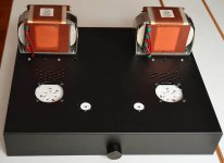
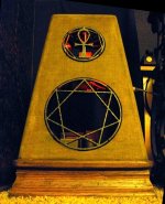
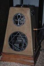
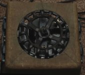
3 watt monoblocks.Telefunken RS242 power tube,transformer coupled to a 6SN7 preamp/driver.Still a few details to finish,like illumination,and some protective screens on the rear.The top vent rotates,operating the stepped attenuator.
Attachments
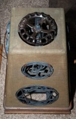
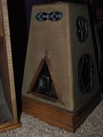
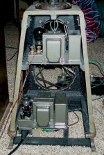
3 watt monoblocks.Telefunken RS242 power tube,transformer coupled to a 6SN7 preamp/driver.Still a few details to finish,like illumination,and some protective screens on the rear.The top vent rotates,operating the stepped attenuator.
Wow! Very creative. Quasi-Ancient style, I like it!
- Home
- Amplifiers
- Tubes / Valves
- Photo Gallery