Steve,
Nice match to the OTL. I wonder, on the line stage, why didn't you use gas VR tubes for the shunt regulators.
That is my favorite color of red. I painted my last excellent speaker design prototype pair, the Ultor-X, that color plus eggshell black.
rca
The reason for not using the VR tubes was that I wanted a valve for the shunt reg so as to kill off the last vestiges of ripple by feeding antiphase ripple from grid back to its plate via a coupling cap.
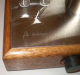
The little adjusting knob on the top of the pre adjusts the amount of feedback, enabling ripple to be tuned out to give a silent background.
The OTL is so quiet that any noise added is immediately noticeable, The ripple killer makes sure there is no chance of noise creeping into the preampand it does regulating duties too.
Yep the red looks great. Glad all of you like it.
The reason for not using the VR tubes was that I wanted a valve for the shunt reg so as to kill off the last vestiges of ripple by feeding antiphase ripple from grid back to its plate via a coupling cap.
The little adjusting knob on the top of the pre adjusts the amount of feedback, enabling ripple to be tuned out to give a silent background.
The OTL is so quiet that any noise added is immediately noticeable, The ripple killer makes sure there is no chance of noise creeping into the preampand it does regulating duties too.
Yep the red looks great. Glad all of you like it.
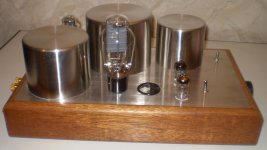
I only see two tubes. Presumably one tube per channel. Are you saying you introduce a small sample of anti-phase hum into the line stage signal amplifier tube? So where are the B+ shunt regulator tubes hiding?
At the front of the preamp there is a black cylinder. This is a German C3g pentode, strapped as a triode. This is the shunt reg tube and it is this that does the antiphase ripple thing.
Oh. I thought that was an electrolytic capacitor. Must be a European thing. I'm not big on using metal shell tubes because they aren't as interesting to look at. That said, the amplifier in my avatar uses a DH metal tube wired as a triode as an input stage and driver through an interstage transformer and it is a 1619, metal equivalent of a 6L6G with a 2.5 volt DH cathode. DH tubes seem to have a magic quality to the sound over sleeved cathodes. The DH output tubes in that amp are 809 run A2. I wanted an amp using all DH tubes. It has very liquid mids and highs but requires near 100 dB speakers as it only outputs 3.25 watts/ch. The bright emitter 809's help offset the lack of glass in the front sockets though.

New PP6550 60 Watts
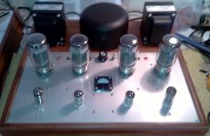
It's a new PP 6550 60 Watts class AB amp made for my cousin.
Input tube is a 6n1p- EV, 6n6p as LTP driver with ixys 10m45s (18mA) and finally 6550 EH in UL. Va=465 Volts, fixed bias Ia=55 mA.
Amp is running flawless till 60 Watts. Clip showed at 75 Watts.
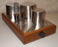
OPTs are Hammond 1650N and PT it''s a custom one winded on a 800 VA core
Sound is full bodied and pleasant for a lot kind of music i listened. From Jazz till hard rock amp sounds great.
Freq response at 50 Watts 25hz - 36Khz, 0db,
Thd : 1.8% at 50 Watts - 1khz, 2.5% at 60 Watts - 1khz, no feedback applied.
Think that all went great and 6n6p LTP looks like hell of a driver for PP purposes if current sourced. LTP Sin waves look absolutely symmetric both phases..
Quiet happy of the result.
Sorry for the bad quality photos...
It's a new PP 6550 60 Watts class AB amp made for my cousin.
Input tube is a 6n1p- EV, 6n6p as LTP driver with ixys 10m45s (18mA) and finally 6550 EH in UL. Va=465 Volts, fixed bias Ia=55 mA.
Amp is running flawless till 60 Watts. Clip showed at 75 Watts.
OPTs are Hammond 1650N and PT it''s a custom one winded on a 800 VA core
Sound is full bodied and pleasant for a lot kind of music i listened. From Jazz till hard rock amp sounds great.
Freq response at 50 Watts 25hz - 36Khz, 0db,
Thd : 1.8% at 50 Watts - 1khz, 2.5% at 60 Watts - 1khz, no feedback applied.
Think that all went great and 6n6p LTP looks like hell of a driver for PP purposes if current sourced. LTP Sin waves look absolutely symmetric both phases..
Quiet happy of the result.
Sorry for the bad quality photos...
Attachments
Hi!It's a new PP 6550 60 Watts class AB amp made for my cousin...
Sorry for the bad quality photos...
Tell us how you have connected one milliammeter in the circuit of four power tubes?
I too want to do so.
Hi!
Tell us how you have connected one milliammeter in the circuit of four power tubes?
I too want to do so.
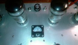
Piece of cake, you just choose each cathode at a time with at least a 4 way selector (black knob). I choose a 5 way one, four for each cathode and one (center) to keep meter neutral ..
Looks interresting, can you please show how did you electrically connected it? Being an ammeter, it has to be in series, so I wonder how did you....Piece of cake, you just choose each cathode at a time with at least a 4 way selector (black knob). I choose a 5 way one, four for each cathode and one (center) to keep meter neutral ..
Best regards,
Thanks
Looks interresting, can you please show how did you electrically connected it? Being an ammeter, it has to be in series, so I wonder how did you....
Best regards,
Thanks
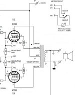
Take a ready made snapshot, Just use a 5 way selector ....Hope it's quiet clear now ...
Regards,
George
Attachments
Take a ready made snapshot, Just use a 5 way selector ....Hope it's quiet clear now ...
Regards,
George
Is this really an ammeter, or a 100 mV voltmeter with the scale changed to read mA?
Most inexpensive moving coil 100 mA ammeters have an internal resistance of order 1 ohm, so putting this in parallel with a 1 ohm resistor will give you a current reading which is around half of the actual cathode current. This still works fine for checking balance, but it won't give an accurate current measurement.
Perhaps you found a very low internal resistance ammeter?
In my case is really an mAmeter. It's definitely in series, between cathode and ground. Measurements checked also with fluke meter, seem right, so it's the one for the job...
Regards,
George
Now I get it, thank you!!Take a ready made snapshot, Just use a 5 way selector ....Hope it's quiet clear now ...
Regards,
George
Best regards
In my case is really an mAmeter. It's definitely in series, between cathode and ground. Measurements checked also with fluke meter, seem right, so it's the one for the job...
Regards,
George
As drawn, the ammeter is in parallel with the 1 ohm resistor between cathode and ground. If you place an external ammeter at the same spot (in parallel) you could likely get the same result. The real test would be to measure the voltage across the 1 ohm resistor with the ammeter disconnected (switch in center position).
I am glad you are happy with this, I just don't want others thinking this solution is guaranteed to work.
Yes. All is my projects...Looks superbly!
Chassis made yourself?
- Home
- Amplifiers
- Tubes / Valves
- Photo Gallery