space to work ??
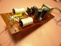
kitchen and living room are the places where I work...
very nice looking...i really need a work space where i can start doing some of this stuff.
kitchen and living room are the places where I work...
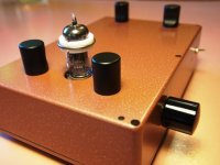
Tony; Are the brown caps Suntan brand and are they Polyester?
i do not know brand, and yes probably polyester, 0.22ufd/400volts...
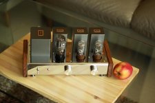
nice!Preamp
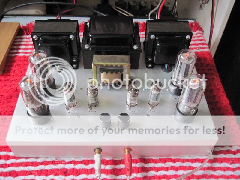
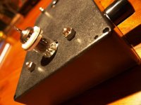
what's in the pots at the rear?
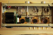

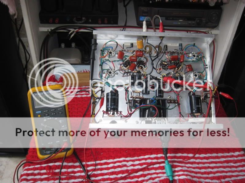
Looks like an amp and very smart. Good work top and bottom.Preamp
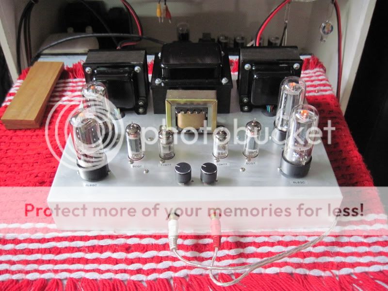
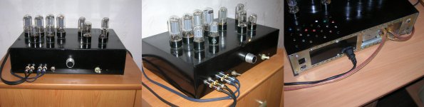
Super Simple Single Stage Tube preamp
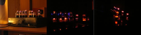
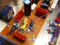
Three very simple single stage tubes preamps I have built of late. A forth (there is one other not shown) has been finished but has some issues. But then again haven't we all.
Three very simple single stage tubes preamps I have built of late. A forth (there is one other not shown) has been finished but has some issues. But then again haven't we all.
Attachments
Three very simple single stage tubes preamps I have built of late. l.
Nice!
can you post a diagram?
any of them phono?
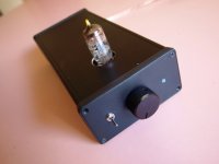
None are phono preamps they are all line level preamps. I'll dig up the schematic but there is three different schematics involved. I'll post the one for the MKIII "The Black" it is the best sounding so far.Nice!
can you post a diagram?
any of them phono?
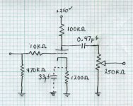
I was asked for the schematic of the Single Stage tube preamp. This schematic has not been evaluated from a sonic point of view but it does have some advantages. It can take any 12Axx tube you want. True plug and play.
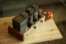
It is not my design it belongs to Suncalc but I know he is happy to share. I have built this one (Hammond case see images in earlier post) but have not had the time to listen to it properly. Build and Share!
It is not my design it belongs to Suncalc but I know he is happy to share. I have built this one (Hammond case see images in earlier post) but have not had the time to listen to it properly. Build and Share!
Attachments
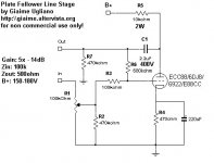
Very easy to fix the gain issues. Remove one or both of the NFB loops. From now building four different versions of the original cct. I would recommend deleting the voltage NFB (resistor from the plate to the grid) but leave in the current FB (un-bypassed cathode R). So do not put a cap across the cathode resistor.I have built a version and used the first schematic you posted. Beautiful sound, but little to much gain!
Easiest way to do it is cut away the plate to grid resistor.
Very easy to fix the gain issues. Remove one or both of the NFB loops. From now building four different versions of the original cct. I would recommend deleting the voltage NFB (resistor from the plate to the grid) but leave in the current FB (un-bypassed cathode R). So do not put a cap across the cathode resistor.
Easiest way to do it is cut away the plate to grid resistor.
I'm just lurking here, but I'm interested.
Which schematic are y'all talking about? (I can't see any plate-to-grid resistor in the schematic just a few posts above...)
Also, won't removing NFB increase the gain? I thought stenak wanted less gain?
Thanks.
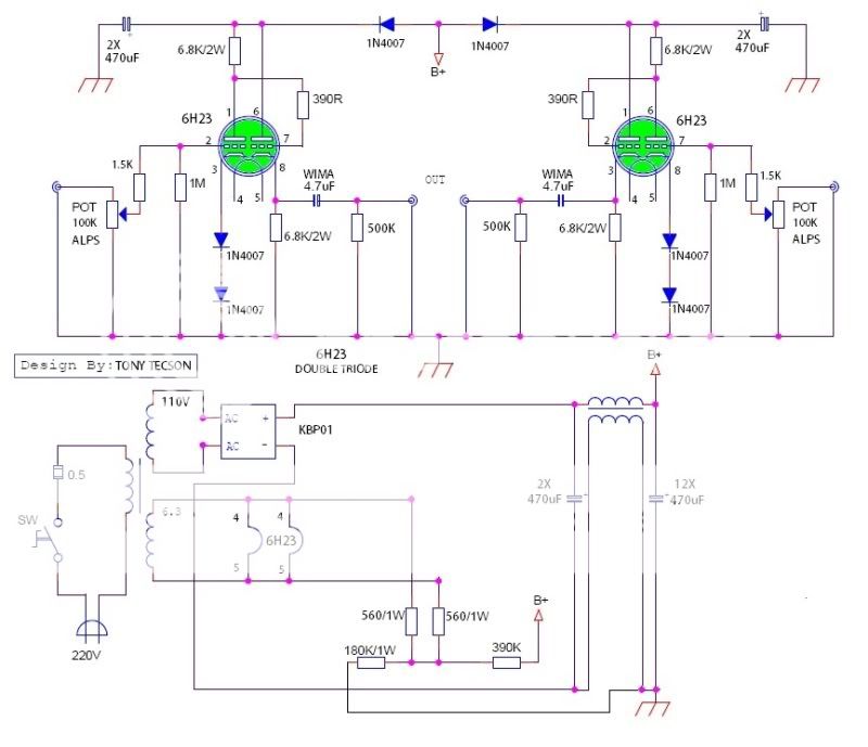
Well this is at least one of the original ccts. Even in the very original there was no bypass cap on the cathode R.
In more recent buils please note I have increased Rp to 28K and reduced Rc to 800ohms.
Rp=28K up from 20K and Rc=800ohms down from 1.1K.
Here are the live measurements:
HT=280V
Plate to GRND voltage = 125V
Cathode drop (bias)=3.6V
Total current draw through both plates added together = 9ma (4.5mA through each plate).
Plate dissipated in each tube = (125 - 3.6) * 4.5mA = 100mW
In even more recent builds drop the plate to grid FB and un-bypass the cathode resistor. So no cap on the cathode resistor.
Attachments
Last edited:
- Home
- Amplifiers
- Tubes / Valves
- Photo Gallery