


Very nice, Airpower!
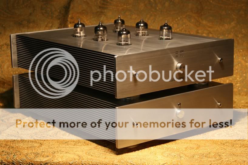
Air Power - Excellent and professional built.
Johnny
Thanks a lot!
tim614Airpower.
Het say!
Cam on!

My 6C33C Push Pull
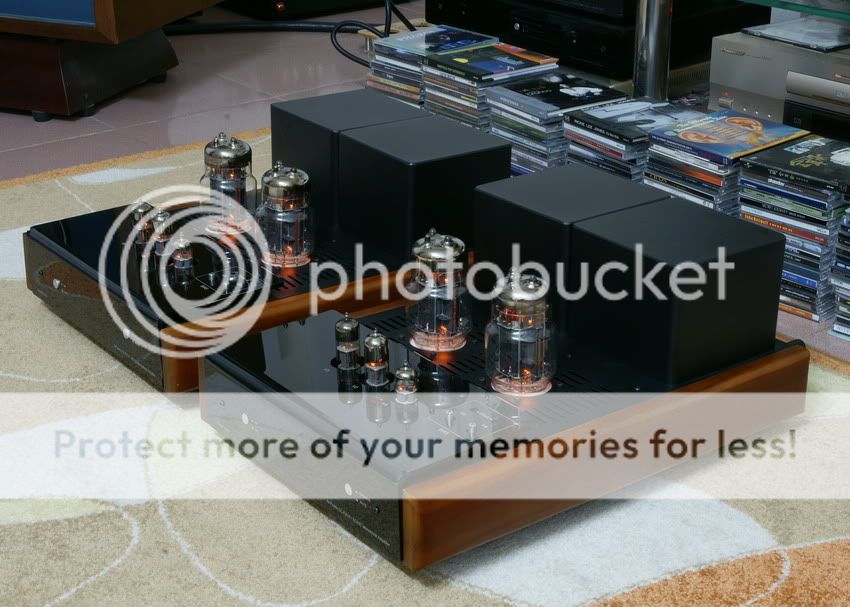

Just beautiful! The best looking build I've seen in a looooong time- thoroughly professional inside & out!
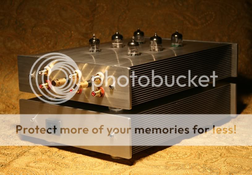
Nice fit on the side panels- a very clean appearance on the top panel - looks like excellent ventilation too.
I notice the bias controls on the top panel and wonder why you chose them to be so "end-user accessible" -is the bias monitored externally?
Only today I was thinking about using pots to set the bias individually instead of the usual "total bias current" and "DC Balance" arrangement. Nice choice!
Congratulations on a gorgeous design!
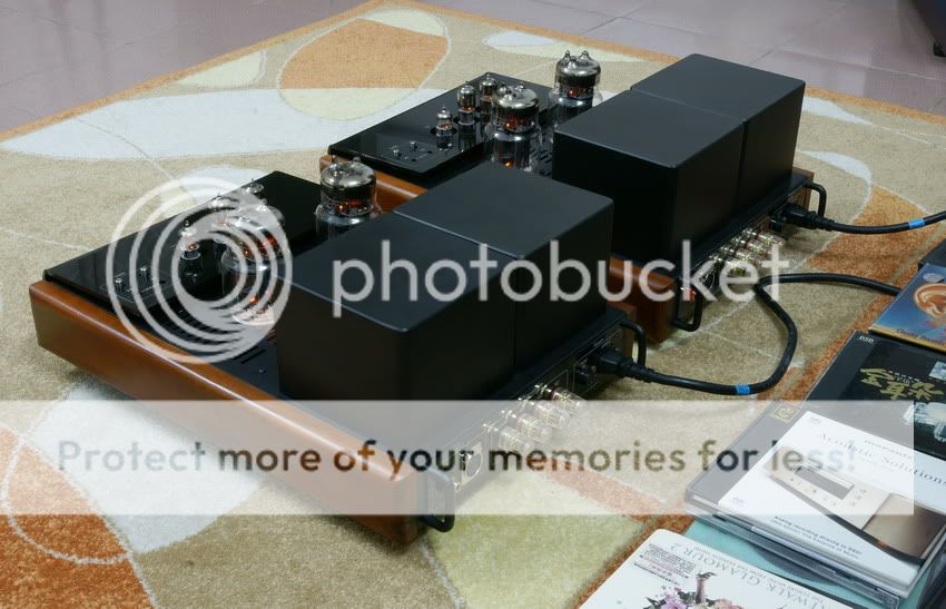
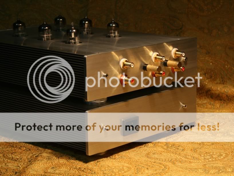
Whose transformers did you use? The power and output are exactly the same size, it appears- so I wonder if you fabricated the cans yourself and fit the transformers inside, or if you found a vendor that just happened to make them the same size?
I do the Power trans and Output trans by my Toroidal winding machine.
The power trans and output trans have the same size and their size are large enough for the cans.
Hey Airpower!
What a gorgeous amp!
That's what I'd like my 13E1 amp to look like once it is
past the prototype stage.
Inspirational!
Steve
Thanks for your compliment!
I also like 13E1 Amp so I want to find tubes for this. Would you like to show me where you bought them?
Regards!

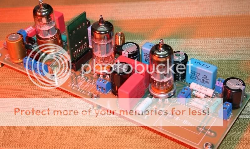
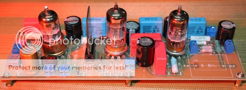
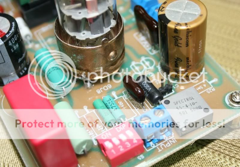
push pull l 84 circuito ken browm renovado
es una renovacion de un push pull de ken browm lo probamos con unas cajas infiniti de 15" 102 db impresionante el rendimiento de esta miniatura
is a renewal of a push pull of what we tried ken Browman infiniti boxes 15 "102 db impressive performance of this miniature
es una renovacion de un push pull de ken browm lo probamos con unas cajas infiniti de 15" 102 db impresionante el rendimiento de esta miniatura
is a renewal of a push pull of what we tried ken Browman infiniti boxes 15 "102 db impressive performance of this miniature
Attachments
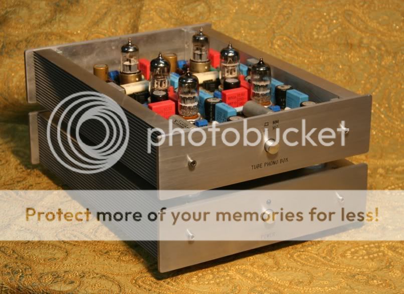
RS 607 Telefunken
hey Guys!
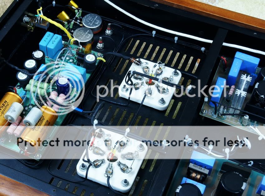
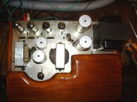
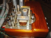
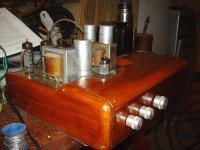
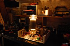
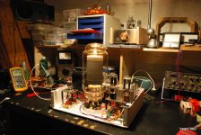
I just finished my 100W? SE amp.
2 rectifier tubes on the right
on the left a 6EM7 which is beefy enough to steer the huge RS607.
I measure well over 30V into 8 ohms (with headphones on)
No distortion I can hear....
No humm either.
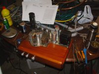
Now the left channel.
The front is going to be ground stainless steel or wood, don't know yet.
the top a glass plate.
hey Guys!
I just finished my 100W? SE amp.
2 rectifier tubes on the right
on the left a 6EM7 which is beefy enough to steer the huge RS607.
I measure well over 30V into 8 ohms (with headphones on)
No distortion I can hear....
No humm either.
Now the left channel.
The front is going to be ground stainless steel or wood, don't know yet.
the top a glass plate.
Attachments
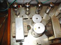
hey Guys!
I just finished my 100W? SE amp.
2 rectifier tubes on the right
on the left a 6EM7 which is beefy enough to steer the huge RS607.
I measure well over 30V into 8 ohms (with headphones on)
No distortion I can hear....
No humm either.
Now the left channel.
The front is going to be ground stainless steel or wood, don't know yet.
the top a glass plate.
stunning. give us some details on the PS
Thanks a lot!
Cam on!
My 6C33C Push Pull
Excellent work Airpower!!!!
Which schematic did you use?
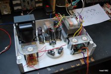
Rs 607 ps
Hi Adamus,
this is what it looks like right now.
I had a lot of trouble getting rid of some 100Hz humm.
Tried about everything, different tubes, shield the transformer, use other diodes, replaced the diodes by tubes, replaced the tubes by diodes, more caps, less caps, more L's... filter the 230 in.
move the transformers around.
2 months of fiddling.
Then a friend said....
put one side of the pre-amp heater to gnd.
done.
gone.
that's why it says 1.1 on the diagram. I'd gone up to 3.6 already....
It sounds.... like a HUGE SE...
gerrit
Attachments
- Home
- Amplifiers
- Tubes / Valves
- Photo Gallery