Jeff, yup quite right.
The output transformer quality is vital in this design and a custom part was used extending to 15Hz and 50Khz at 250W. The 15Hz 1.4% 2nd harmonic criteria was used in determining low end core size.This took some time to optimise and was done by brain and calculator and alot of emails. The tricky part is to keep the upper frequency response up. What alot of folk don’t realise is as the size goes up, the problem with the anode to UL tap leakage inductance gets progressively worse and to avoid ringing various snubber networks are used and snubber dissipation gets higher je the size. Yet circuit is stable with global 36dB nfb. Despite the lower working Z with parallel p-p, size is the biggest penalty with electrical parameters, more copper implies higher internal C’s and the conflict with leakage inductance grows. Facit, don’t go for a montrous large design unless one really knows what one is up against.
20dB global nfb used. Used 10 ohm in each cath leg which reduces IM thd. By far the most influencial component in nulling thd is a pot in the driver stage anodes. (per Williamson) This tweak ensures optimum harmonic null.
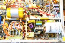
Another issue with power. Most transformer manufacturers ignore insulating the screws through the transformer E&I laminations, the eddy currents from stray leakage inductance is quite high and with a case to case s/c or within the lid of a drop-through types acts as a part shorted turn. This will waste considerable power and make the screws (M6) to get quite hot.. The photo shows a fiber washer insulating the lid. This even applies to the output transformer. The difference between doing it and not doing it amounts to about 50W wastage on a 650W core !!
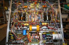
There is alot of detail which in other designs wouldn’t be apparent. Fuses against fire are obvious. This requires sensing circuitry if e.g the neg bias fails. Mains transformer windings are all sep fused except 6.3V 35A winding which has thick enough wiring on a short to blow the mains fuse. The only way to ensure sensible AC line input fuse rating is to use an input soft-start ballast which will drop out & reset on a cycle per cycle basis on intermittant mains contact.
One soon realises the conjestion and lack of physical space gets used up. photo of pfc section. The copper 6.3V busbars can just be made out 15% down from top
richj
The output transformer quality is vital in this design and a custom part was used extending to 15Hz and 50Khz at 250W. The 15Hz 1.4% 2nd harmonic criteria was used in determining low end core size.This took some time to optimise and was done by brain and calculator and alot of emails. The tricky part is to keep the upper frequency response up. What alot of folk don’t realise is as the size goes up, the problem with the anode to UL tap leakage inductance gets progressively worse and to avoid ringing various snubber networks are used and snubber dissipation gets higher je the size. Yet circuit is stable with global 36dB nfb. Despite the lower working Z with parallel p-p, size is the biggest penalty with electrical parameters, more copper implies higher internal C’s and the conflict with leakage inductance grows. Facit, don’t go for a montrous large design unless one really knows what one is up against.
20dB global nfb used. Used 10 ohm in each cath leg which reduces IM thd. By far the most influencial component in nulling thd is a pot in the driver stage anodes. (per Williamson) This tweak ensures optimum harmonic null.
Another issue with power. Most transformer manufacturers ignore insulating the screws through the transformer E&I laminations, the eddy currents from stray leakage inductance is quite high and with a case to case s/c or within the lid of a drop-through types acts as a part shorted turn. This will waste considerable power and make the screws (M6) to get quite hot.. The photo shows a fiber washer insulating the lid. This even applies to the output transformer. The difference between doing it and not doing it amounts to about 50W wastage on a 650W core !!
There is alot of detail which in other designs wouldn’t be apparent. Fuses against fire are obvious. This requires sensing circuitry if e.g the neg bias fails. Mains transformer windings are all sep fused except 6.3V 35A winding which has thick enough wiring on a short to blow the mains fuse. The only way to ensure sensible AC line input fuse rating is to use an input soft-start ballast which will drop out & reset on a cycle per cycle basis on intermittant mains contact.
One soon realises the conjestion and lack of physical space gets used up. photo of pfc section. The copper 6.3V busbars can just be made out 15% down from top
richj
Attachments
Nice! I see you put both channel's PSU on one chassis. I thought about that. I started building my PSU chassis last weekend. I opted for seperate chassis and didn't put things so close together because I am not so sure I'd get the layout so well done that I could get away with such close quarters.
Very clean!
Is the wood Wengae (or Wenge) ?
Nice dense wood, good for musical instruments.
Are the caps painted or something more serious?
Does the dual PS feed a similar dual-amp-in-one chassis?
Love those amphenol connectors! Lately I've been favoring the Bendix style bayonets.
Cheers!
Is the wood Wengae (or Wenge) ?
Nice dense wood, good for musical instruments.
Are the caps painted or something more serious?
Does the dual PS feed a similar dual-amp-in-one chassis?
Love those amphenol connectors! Lately I've been favoring the Bendix style bayonets.
Cheers!
Very perceptive - Wenge it is. Careful with those slivers; they are brutally painful.
Caps are just the typical ASC motor runs, painted black. The amps proper will have their own local sets of caps as well.
I plan on monoblocks for the amplifiers for an overall three chassis design. This will give me plenty of room to provide magnetic spacing between the filament transformers and audio transformers. For the record, the reason for two IEC inlets is NOT for the two power supplies. One inlet feeds both power supplies in complete. The other inlet is dedicated for the DHT filaments, and will be supplied from a regulated source to variac. That way, I can play around with the voltage on the filaments easily. I also like the idea of the high common mode and differential mode filtering the Sola ferroresonant transformers give me. From what I understand, Lynn is preferential to a filament supply somewhere around 109V.
I'll post a shot of the guts when ready. Just a few more solders to make.
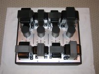
zigzagflux said:Guts.
Just have to land the copper bus to the Amphenol, and she's done.
Can't make it out...youv'e gotton away with a part empty box ?
richj
Make sure the photo's are below 100kb. Best done by altering the image size to something like 640*480 and save as jpg with some compression.How do you fix the thumbnails? Gotta a lotta photos but they are too big, and a simple text-link is boring.
richwalters
Did you have to wire your box in layers?
"Using KT88’s and 575VB+ the design goal is achieved with outputs exceeding 250W per channel extracted. (Strangely I got 650W in bridge mode, this seems high)"
What load impedance did you use in bridge mode vs. stereo?
Cheers
Did you have to wire your box in layers?
"Using KT88’s and 575VB+ the design goal is achieved with outputs exceeding 250W per channel extracted. (Strangely I got 650W in bridge mode, this seems high)"
What load impedance did you use in bridge mode vs. stereo?
Cheers
Michael Koster said:richwalters
Did you have to wire your box in layers?
"Using KT88’s and 575VB+ the design goal is achieved with outputs exceeding 250W per channel extracted. (Strangely I got 650W in bridge mode, this seems high)"
What load impedance did you use in bridge mode vs. stereo?
Cheers
Nup, the first was the thick twisted heater wiring and to avoid volts drop interconnected each quad to another, then buss all sockets at transformer end. Cumbersome but although I get darned good performance out of 6550's they are sensitive to heater/emission variations. Compared to some brand 88's, 6550's can take a good 15mins to get fully settled down.
As for bridge mode, I'm going to recheck this more seriously.- I used 8 ohm o/ps on amp into a 4 ohm load, and I knew the transfer match wasn't optimal. 8 Ohms on many tube amp output transformers is codged up using a parallel winding and two series and this poses a lossy problem. Far better to use 4 ohm o/ps i.e double parallel windings in series and use a 2 ohm load. This is what alot of studios use.
Changing tube amp secondaries from designated isn't the done thing as different winding configurations can lead to phase and square wave problems.
I use balanced 600 ohm and best way is to use reed relays and two identical input transformers and change input on one channel.
more anon.
richj
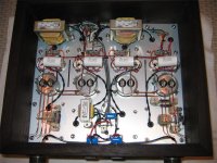
My first attempt to build something out of my own head and thinking and by the way learning to calculate implementation of every singel component. Make every singel valve work at its best centerpoint. Some 15 years ago. At that time there where no help at internet, so I had to shoop many books and read a lot.
Once ready it workt at once, just some corrections of the stabdiodes for the smalltriodes and little correction of the NFB.
Messured very nice at the oscilloscope, driven with different monstertraps at the outputterminals.
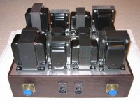
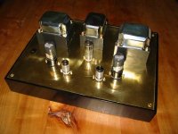
Dynaco mk3 outputtransformators driven by Svetlana 6550s in ULPP low voltage klassA. The sound is like a very good transistoramp (nothing), I mean there is very little cooloration of the sound.")
(Second from left, is an old GE, they never die)
Once ready it workt at once, just some corrections of the stabdiodes for the smalltriodes and little correction of the NFB.
Messured very nice at the oscilloscope, driven with different monstertraps at the outputterminals.
An externally hosted image should be here but it was not working when we last tested it.
An externally hosted image should be here but it was not working when we last tested it.
An externally hosted image should be here but it was not working when we last tested it.
An externally hosted image should be here but it was not working when we last tested it.
Dynaco mk3 outputtransformators driven by Svetlana 6550s in ULPP low voltage klassA. The sound is like a very good transistoramp (nothing), I mean there is very little cooloration of the sound.
(Second from left, is an old GE, they never die)
Ragnwald said:
Dynaco mk3 outputtransformators driven by Svetlana 6550s in ULPP low voltage klassA. The sound is like a very good transistoramp (nothing), I mean there is very little cooloration of the sound.
(Second from left, is an old GE, they never die)
The only transistor or mosfet amp that has come anywhere near the < tube sound> is the simplest Maplin amp, an early mos Jap design from 1978 which I mentioned in another thread. The rest are basically all the same complementary pairs poorly designed overheated class A drivers which eventually fail. The number of SS amps I've repaired is countess and nearly have all the same problems.
richj
It's not the worlds greatest sound, but I like it. It kind of grows on you....
It sound relaxed, it does not wear you out. Whit my Fostex FE107E single driver QWTP it is just right.
I like simple music, singer/songwriter-stuff; small jazz-fusion combo's; folk/folkrock. All this sounds great. I'm a happy man.........
Although I like to build stuff; so I'm already thinking up new plans.....
An 807 PP is on its way; combined with an Fostex FE208 hornsystem.
I'm a busy man....
- Home
- Amplifiers
- Tubes / Valves
- Photo Gallery