andersss2013 interesting amp,is that some Brocott wire there? Re your amp sounding crap,run some tests especially at very LF and HF to see how it performs at low and max OP. Your tfmr's look big enough, but your OPT may be saturating & have too much interwinding C or any coupling may be rolling off the HF, tests will tell. Start off testing just the IP stage,then work through,oh and monitor HT whilst your at it, it may be sagging. Lastly check for ground loops,some pics of the unside would be good, might be able to spot something.
Democles, did I spot some ceramic wafers out of a Tek plugin or Hickok scope? They're good but tricky to solder as good as the ladies at Tek.
The problem i have with home painting is the paint comes off around holes and edges, even with etching primer, nice job.
Wavebourn, at first I thought you'd used a bread bin for the amp chassis, it's an interesting design.
Good work lads, Andy.
Thank you for asking!
Well, I thought it was splendid at first but have become more and more critical.
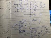
I have a steady hum probably from bad filtered B+. I use only a CLC filter 47u+5H+47u. Have learnt to ignore the hum somehow. I think it is lacking som highs, seems to roll off from 15-16k. Can't hear much over 13k anyway. It goes really deep, house shaking, type base but it definitely lacks punch compared to other amplifiers I'v built. To sum up, it hums, lacks highs and swampy bass but other than that... Maybe my schematic was too simple. Surely could need some good advice, haven't given up on the thing yet.
Good luck with it.! You are way beyond my DIY abilities winding your own OPTs. I like the look in any case!
BTW, it sounds like you built it a long time ago, is that right? How long ago?
A new version of Hercules prototype, almost ready.
Class A1 push-pull amp, 45W per channel.
Unbalanced RCA and transformer balanced inputs, 0 dB.
4, 8, 16 0hm speaker outputs.
Continuous variable damping factor cоntrоl, from negative output resistance active servо-damping) tо positive (current drive). Almost inaudible soft saturation when overdriven.
Very nice build! Looks really good, love that red colour.
About that negative output impedance.
Do you mean the output of the push pull amp? If this is so, then with a negative output impedance
will this give chance to oscillation when loaded with an inductive load?
Very nice build! Looks really good, love that red colour.
About that negative output impedance.
Do you mean the output of the push pull amp? If this is so, then with a negative output impedance
will this give chance to oscillation when loaded with an inductive load?
Absolutely. With any load, if you over-compensate DCR, it starts oscillating.
")
I was laughing while reading marketing numbers about Damping Factor that does not matter much as soon as output resistance of an amp is significantly lower than DCR of speakers.
andersss2013 interesting amp,is that some Brocott wire there? Re your amp sounding crap,run some tests especially at very LF and HF to see how it performs at low and max OP. Your tfmr's look big enough, but your OPT may be saturating & have too much interwinding C or any coupling may be rolling off the HF, tests will tell. Start off testing just the IP stage,then work through,oh and monitor HT whilst your at it, it may be sagging. Lastly check for ground loops,some pics of the unside would be good, might be able to spot something.
Democles, did I spot some ceramic wafers out of a Tek plugin or Hickok scope? They're good but tricky to solder as good as the ladies at Tek.
The problem i have with home painting is the paint comes off around holes and edges, even with etching primer, nice job.
Wavebourn, at first I thought you'd used a bread bin for the amp chassis, it's an interesting design.
Good work lads, Andy.
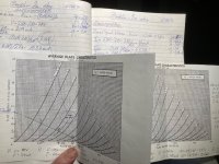
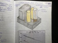
Thank you for all your comments, sure need all help I can get. More pics of inside coming. My output design was for a 400V, 3.5K and a max I of 90 mA. The output transformer is a EI 96 core. Calculated the necessary inductance to 14H. Calculated inductance leakage is 7.4 mH and interleave capacitance is 250pF. The gap calculated based on the Hanna curve is 1.8 mills. I cannot measure what real values are just hoping. but i have a simple signal generator, oscilloscope and multimeters. HT is rather steady at 415-420V. Didn't "pot" the transformer yet because i was afraid I would have to take the apart. maybe potting in wax or shellack will improve a little.
Good luck with it.! You are way beyond my DIY abilities winding your own OPTs. I like the look in any case!
BTW, it sounds like you built it a long time ago, is that right? How long ago?
Thank you for kind words! I did the design, schematic, sketches and necessary calculations in 2018 and built it mostly in the winter 2019. last winter I built a phono preamp for 78rpm. Now I'm back at this amp trying to improve it.
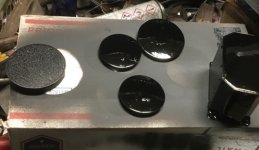
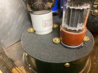
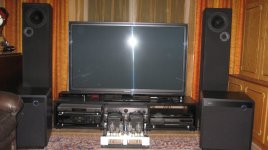
posting some more pics of the breadboard amplifier. Made my own insulation wax paper with beeswax and acid free paper. There is a metal case inside wooden box. Signal leads going inside a copper tube from inlet to selector switch to volume pot and up to the 6sn7. A design i saw in a military radio equipment of some kind.
Attachments
-
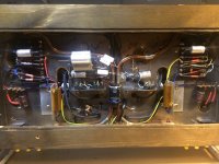 image1.jpg598.5 KB · Views: 593
 -
 IMG_7888.jpg462 KB · Views: 238
 -
 IMG_7876.jpg518.8 KB · Views: 213
 -
 IMG_7874.jpg345.8 KB · Views: 204
 -
 IMG_1486.jpg71.4 KB · Views: 225
 -
 IMG_0025.jpg104.8 KB · Views: 583
 -
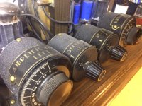 image4.jpg667 KB · Views: 581
 -
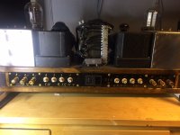 image3.jpg488.7 KB · Views: 580
 -
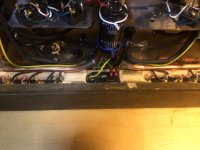 image2.jpg512.1 KB · Views: 583
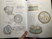
posting some more pics of the breadboard amplifier. Made my own insulation wax paper with beeswax and acid free paper. There is a metal case inside wooden box. Signal leads going inside a copper tube from inlet to selector switch to volume pot and up to the 6sn7. A design i saw in a military radio equipment of some kind.
Did you make the volume pot and selector cases? Can you post pix of the build?
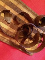
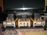
Yes, they are made of 3" and 2.5" pieces of exhaust pipes for cars and sheet metal for front and back. Spotwelded with mig and then lead soldered. The stands are made of sheet metal riveted to the housing. Rivets are made of brass nails. Slot screw, not so easy to find around here, ordered from UK. Paint is a special wrinkle paint used for valve covers for a pair of old mopars in the garage. Problem is that paint can't be imported anymore due to restrictions. Sad because transformer covers aren't painted yet Will look for more pics.
Will look for more pics.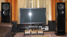
- Home
- Amplifiers
- Tubes / Valves
- Photo Gallery