
Not a Borg Cube
https://files.diyaudio.com/forums/i...images/attach/jpg.gifms/images/attach/jpg.gif
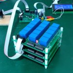
I have a long term project on the go, it is to be a fully automated tube tester designed to eliminate many manual switching operations.
Solid state switching of the valve socket pins is not an option due to current leakage.
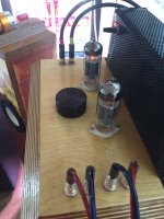
I have designed my relay cube it has 5 inputs (anode, screen, grid, ground, Heater/filament) and 9 outputs, one for each tube socket pin.
45 relays are fed power and data via a single ribbon cable from the micro PCB (my design) so it can switch 5^9 combinations (1953125 combinations).
I have written some C code to test the cube and it seems to work fine, only actual testing will show how much leakage I will have from the high voltage to the bias supply.
The PCB is 100mm x 100mm so it would actually need another layer to make a cube.
BTW the high voltage, DC heater and bias supplies (micro controlled) PCB's have been designed, built and tested. I'm going to try measuring transconductance at normal and reduced heater voltage to see if it will predict tube life.
The 12V connector on the edge of the PCB is not used as my micro board can supply enough current for over 12 relays on at a time, normally only 9 relays will be energised at one time.
I will be able with the micro controlled cube test current leakage between any two element in whatever direction I choose.
All relay switching will take place a near zero voltage. The tracks are good for 2.5A continuous and maybe 3A for a shorter period.
I have tried pulse testing of tubes and have found it unsatisfactory for many applications, some vintage tubes only seem to start having grid current problems after running for a while, my design allows for over 30 watts anode dissipation for many hours at a time.
I intend to use a small receipt printer to print out a report on the tube. The printer will be the main data output, maybe bluetooth, operating systems seem to date quite fast when you are my age. The device will be stand alone with auto and fully manual modes of operation, I expect to have some output terminals on the tube tester so it can supply adjustable regulated anode, screen, heater and bias voltages for bench top experiments. BTW all regulated supplies are linear for low noise after all the device needs to measure micro amps with low noise.
BTW this is related to tube amps, I've built a few over the past 50 years.
Ken Kranz
https://files.diyaudio.com/forums/i...images/attach/jpg.gifms/images/attach/jpg.gif
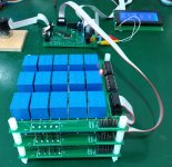
I have a long term project on the go, it is to be a fully automated tube tester designed to eliminate many manual switching operations.
Solid state switching of the valve socket pins is not an option due to current leakage.
I have designed my relay cube it has 5 inputs (anode, screen, grid, ground, Heater/filament) and 9 outputs, one for each tube socket pin.
45 relays are fed power and data via a single ribbon cable from the micro PCB (my design) so it can switch 5^9 combinations (1953125 combinations).
I have written some C code to test the cube and it seems to work fine, only actual testing will show how much leakage I will have from the high voltage to the bias supply.
The PCB is 100mm x 100mm so it would actually need another layer to make a cube.
BTW the high voltage, DC heater and bias supplies (micro controlled) PCB's have been designed, built and tested. I'm going to try measuring transconductance at normal and reduced heater voltage to see if it will predict tube life.
The 12V connector on the edge of the PCB is not used as my micro board can supply enough current for over 12 relays on at a time, normally only 9 relays will be energised at one time.
I will be able with the micro controlled cube test current leakage between any two element in whatever direction I choose.
All relay switching will take place a near zero voltage. The tracks are good for 2.5A continuous and maybe 3A for a shorter period.
I have tried pulse testing of tubes and have found it unsatisfactory for many applications, some vintage tubes only seem to start having grid current problems after running for a while, my design allows for over 30 watts anode dissipation for many hours at a time.
I intend to use a small receipt printer to print out a report on the tube. The printer will be the main data output, maybe bluetooth, operating systems seem to date quite fast when you are my age. The device will be stand alone with auto and fully manual modes of operation, I expect to have some output terminals on the tube tester so it can supply adjustable regulated anode, screen, heater and bias voltages for bench top experiments. BTW all regulated supplies are linear for low noise after all the device needs to measure micro amps with low noise.
BTW this is related to tube amps, I've built a few over the past 50 years.
Ken Kranz
Attachments
Gain reduction modifications have been testing for two weeks and it appears to have had no audible negative effects, all positive. Zero noise from the preamp makes it through anymore. It's dead silent at last. It certainly seems to have quite the synergy with my old Tannoy Super Reds.
The only mild annoyance left is the mains transformer buzzes slightly which is quietly audible in a silent room. I've made sure the end bells are fully tight so I'd guess my inner tube rubber vibration dampers are insufficient damping. I really like these electro-harmonix 6CA7's as they sound great, they look great, they seem well made and they are not wildly expensive.
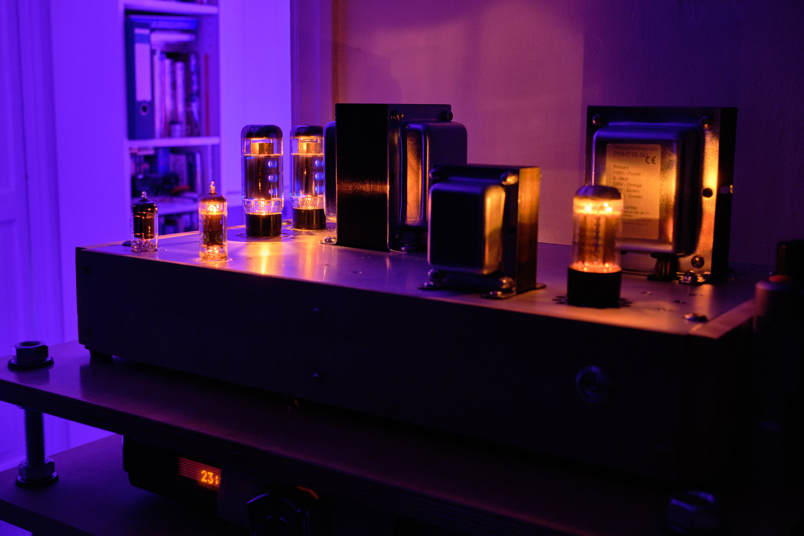


The only mild annoyance left is the mains transformer buzzes slightly which is quietly audible in a silent room. I've made sure the end bells are fully tight so I'd guess my inner tube rubber vibration dampers are insufficient damping. I really like these electro-harmonix 6CA7's as they sound great, they look great, they seem well made and they are not wildly expensive.
Nice amp koldby. I am also using 4x6C33 OTL monos. Love the sound. Mine is Transcendent design. No doubt similar.
Well to my knowledge Transcendent is not a circlotron. I think it is kind of a totempole design. The amp I made has zero feedback.
Agreed. They will have their own unique sonic signature.
There may be some similarity as they are both OTL, fairly high power, and use 6C33C as power tubes.
Bruce Rozenblit (designer) is bluntly bullish about his design vs other OTL") I expect they all have their merits. He argues for feedback. I have a switch that sets 2 levels of feedback. With the switch closed, the amplifier has a forward voltage gain of 22 db. With S1 open, the amplifier has a forward voltage gain of 28 db. There is no question it changes the sonic profile. The resistors used in the feedback loop are also critical to the sound.
I expect they all have their merits. He argues for feedback. I have a switch that sets 2 levels of feedback. With the switch closed, the amplifier has a forward voltage gain of 22 db. With S1 open, the amplifier has a forward voltage gain of 28 db. There is no question it changes the sonic profile. The resistors used in the feedback loop are also critical to the sound.
There may be some similarity as they are both OTL, fairly high power, and use 6C33C as power tubes.
Bruce Rozenblit (designer) is bluntly bullish about his design vs other OTL
I expect they all have their merits. He argues for feedback. I have a switch that sets 2 levels of feedback. With the switch closed, the amplifier has a forward voltage gain of 22 db. With S1 open, the amplifier has a forward voltage gain of 28 db. There is no question it changes the sonic profile. The resistors used in the feedback loop are also critical to the sound.Hi Ken,
great project!
Excellent. Many people using pulse or fast stepping / sweeping testing setups (hence, almost any) forget that a tube system changes mechanical dimensions during warm up, hence parameters change during warm up. This might not be a big deal with small signal tubes which run at a fraction of their max Pa, but with power tubes (even small ones), often run at 80% or more of max Pa continously (think SE amps), tube system temperature *does* make a difference when measuring the parameters.
Kind regards, Tom
great project!
I have tried pulse testing of tubes and have found it unsatisfactory for many applications, some vintage tubes only seem to start having grid current problems after running for a while, my design allows for over 30 watts anode dissipation for many hours at a time.
Excellent. Many people using pulse or fast stepping / sweeping testing setups (hence, almost any) forget that a tube system changes mechanical dimensions during warm up, hence parameters change during warm up. This might not be a big deal with small signal tubes which run at a fraction of their max Pa, but with power tubes (even small ones), often run at 80% or more of max Pa continously (think SE amps), tube system temperature *does* make a difference when measuring the parameters.
Kind regards, Tom
Just finish SE UL 6P41S with 6N2P driver, OPT XSE-10-5k-8 Edcor, 3.6w clean output before clipping and THD 1.15% @2W. I am quite happy with the result first time using this tube, I must say I came across a little better result with other tubes like the 6W6 in this configuration but still very happy.
I found difficult spot the right bias for the 6P41S then on test session find 800 ohm with parallel 100uF cap with B+290 the right one, also with the driver I try ECC81,82 and 83 then decide for the ECC83/6NP2....all the best.
I found difficult spot the right bias for the 6P41S then on test session find 800 ohm with parallel 100uF cap with B+290 the right one, also with the driver I try ECC81,82 and 83 then decide for the ECC83/6NP2....all the best.
Attachments
Member
Joined 2009
Paid Member
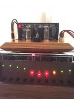
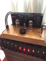
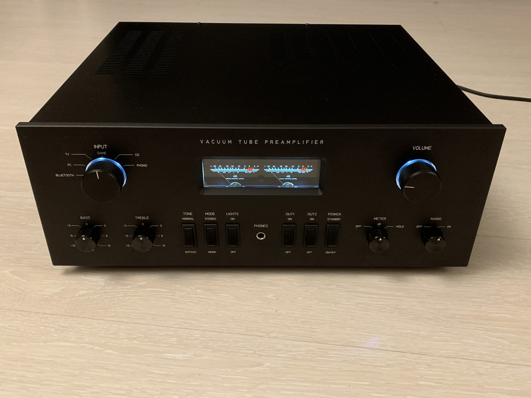
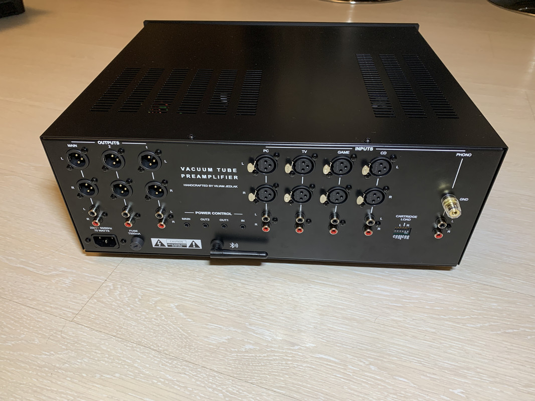
Hey, here is my new preamp I've recently finished. Well, its hybrid, but contain some tubes... full of features, many inputs (including bluetooth) and many switchable outputs, remote, tone controls, headphone amp etc. Its based on some sort of combination of mc c2200/2500 and other mods that fit my needs...
Here is video how it works:
IMG_3092.MOV - Google Drive
Here is full image gallery:
Preamp - Google Drive
if you want to read more about build below is link on article that describes the build, its in slovak language so you can use google translator on page to make it understandable for you SVETELEKTRO • Hybridny predzosilňovač
full of features, many inputs (including bluetooth) and many switchable outputs, remote, tone controls, headphone amp etc. Its based on some sort of combination of mc c2200/2500 and other mods that fit my needs...
An externally hosted image should be here but it was not working when we last tested it.
Here is video how it works:
IMG_3092.MOV - Google Drive
Here is full image gallery:
Preamp - Google Drive
if you want to read more about build below is link on article that describes the build, its in slovak language so you can use google translator on page to make it understandable for you
SVETELEKTRO • Hybridny predzosilňovačthanks no chance to make such a panel at home for me, its 3rd party fabrication from company that got its own program where you can design own panel and let them produce it, i dont know if that violet some forum rules or not i could post link for it here? (oh, i will send you to PM) Rest iron chassis parts I drew in corel and let laser cut and bend according to my design in another metal specialised company, rear labels are UV printed.
no chance to make such a panel at home for me, its 3rd party fabrication from company that got its own program where you can design own panel and let them produce it, i dont know if that violet some forum rules or not i could post link for it here? (oh, i will send you to PM) Rest iron chassis parts I drew in corel and let laser cut and bend according to my design in another metal specialised company, rear labels are UV printed.https://files.diyaudio.com/forums/i...images/attach/jpg.gifms/images/attach/jpg.gif
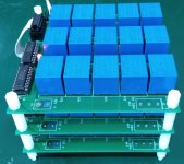
I have a long term project on the go, it is to be a fully automated tube tester designed to eliminate many manual switching operations.
Solid state switching of the valve socket pins is not an option due to current leakage.
I have designed my relay cube it has 5 inputs (anode, screen, grid, ground, Heater/filament) and 9 outputs, one for each tube socket pin.
45 relays are fed power and data via a single ribbon cable from the micro PCB (my design) so it can switch 5^9 combinations (1953125 combinations).
I have written some C code to test the cube and it seems to work fine, only actual testing will show how much leakage I will have from the high voltage to the bias supply.
The PCB is 100mm x 100mm so it would actually need another layer to make a cube.
BTW the high voltage, DC heater and bias supplies (micro controlled) PCB's have been designed, built and tested. I'm going to try measuring transconductance at normal and reduced heater voltage to see if it will predict tube life.
The 12V connector on the edge of the PCB is not used as my micro board can supply enough current for over 12 relays on at a time, normally only 9 relays will be energised at one time.
I will be able with the micro controlled cube test current leakage between any two element in whatever direction I choose.
All relay switching will take place a near zero voltage. The tracks are good for 2.5A continuous and maybe 3A for a shorter period.
I have tried pulse testing of tubes and have found it unsatisfactory for many applications, some vintage tubes only seem to start having grid current problems after running for a while, my design allows for over 30 watts anode dissipation for many hours at a time.
I intend to use a small receipt printer to print out a report on the tube. The printer will be the main data output, maybe bluetooth, operating systems seem to date quite fast when you are my age. The device will be stand alone with auto and fully manual modes of operation, I expect to have some output terminals on the tube tester so it can supply adjustable regulated anode, screen, heater and bias voltages for bench top experiments. BTW all regulated supplies are linear for low noise after all the device needs to measure micro amps with low noise.
BTW this is related to tube amps, I've built a few over the past 50 years.
Ken Kranz
Nice work Ken!
This is exactly the problem with pulse digital tester. Good for small signal tubes, but not for power tube when heat and duration matter.
Seems like you built a switch matrix and the linear PS (programmable ?) you need to test and measure a tube under analog condition. That would be also perfect to burn in tubes.
I am sure you've measured the inherited resistance of the relay(s).
I remember using a simple manual switch matrix when I was younger and the additional R for each switch rendered the model unusable when low resistance is needed (a few ohm).
Cheers,
Brice.
Pulse tube tests vs 'CW'....
Agreed. Contrary to what I wrote here 3D tube curves using an el'Cheapo tube tester (post # 6) my brief look at comparing the u Tracer (pulsed tester) to my 'el Cheapo' (full wave rectified anode voltage applied) does show a significant difference (in results for the EH6CA7 results below). The first image shows a comparison between the uTracer and el Cheapo using a test resistor (reasonable agreement) whilst the second image shows the anode current comparison for the two testers:
The el Cheapo shows the increase in Ia over the time it takes to do 81 sweeps, about 4 minutes (solid traces) compared to the uTracer (measured points represented as points) where strangely the current decreases from the first sweep to the last!
https://files.diyaudio.com/forums/i...images/attach/jpg.gifms/images/attach/jpg.gif
I have tried pulse testing of tubes and have found it unsatisfactory for many applications, some vintage tubes only seem to start having grid current problems after running for a while, my design allows for over 30 watts anode dissipation for many hours at a time.
Ken Kranz
Agreed. Contrary to what I wrote here 3D tube curves using an el'Cheapo tube tester (post # 6) my brief look at comparing the u Tracer (pulsed tester) to my 'el Cheapo' (full wave rectified anode voltage applied) does show a significant difference (in results for the EH6CA7 results below). The first image shows a comparison between the uTracer and el Cheapo using a test resistor (reasonable agreement) whilst the second image shows the anode current comparison for the two testers:
The el Cheapo shows the increase in Ia over the time it takes to do 81 sweeps, about 4 minutes (solid traces) compared to the uTracer (measured points represented as points) where strangely the current decreases from the first sweep to the last!
Attachments


And an interesting speaker just visible in the last photo
is a Tabaq with Tang Band W5-2143 and additional tweeter ...all the best
Wiliks congrats for the beautiful built, actually more than a diy look like a professional amp just out of the factory, I guess lots of work there, I check your schematic and I am very interested on the RIAA circuit you use, did you perform some test ? ...all the best
I did take a look at his site using the link he posted, there is a schematic where RIAA is mentioned.
I am particularly interesed in his tone control circuit. Could not detect it on the schematics published there, but I may have overlooked that of course.
- Home
- Amplifiers
- Tubes / Valves
- Photo Gallery