Koba, what's your experience with Kemet caps? I've alus thought of them as being a bit crap, yon green puppet frog keeps popping into my head too when I see them on Farnell. This is based completely on prejudice though, it's easy to get a bit sniffy about certain makes of parts if your not carefull.
Like the on/off sw, swanky and must have a go at the way you do your OPT's, anything that saves a few bob in that dept has to be worth a try.
Andy.
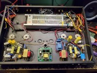
Love them. Never had a failure. There's a guy in the Netherlands who sells them on eBay for about 5$ a piece, and you can still get them through the usual channels, too. Those Kemet caps are the voltage doubler caps.
Here's the datasheet: https://content.kemet.com/datasheets/KEM_A4024_PEH534.pdf
The power switch is a momentary button connected to an "on off" board so it's got touch power.
Thank for the PSU details
Looks interesting, and expecting more photos of your build.
Thanks. It's my first build using a steel chassis and knockout punches instead of a step bit. Waiting on a biasing board which seems to be waiting to clear customs or the plane crashed into the sea. Then I will resume.
Last edited:
I've been using those Kemet caps since they were Rifa, and I love them dearly too.Love them. Never had a failure.
Very robust, stable, long-lasting and perform great. Probably among my top-3.
Thanks both for the lowdown on Kemet caps, I'll bear them in min
d next time I do an order, they're usually cheaper than your Vishay/Rubicon/Panasonics.
The new avatar is bit striking koba, is that some sort of duck, or an abstract painting? Looks like two birds playing cards, might be an acid flashback or too much coffee : )
Andy.
d next time I do an order, they're usually cheaper than your Vishay/Rubicon/Panasonics.
The new avatar is bit striking koba, is that some sort of duck, or an abstract painting? Looks like two birds playing cards, might be an acid flashback or too much coffee : )
Andy.
The birds in my avatar are a recurring theme by a certain Toronto street artist.
An externally hosted image should be here but it was not working when we last tested it.
I think it will be powered up today. Just a few more wires to run.
Looks great anyway!
Thanks, Joe! The only Chinese electros (Chenxing - top middle) will be replaced tomorrow with UCC when they get here, too.
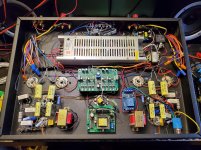
Here's the top...
Just two wires (gNFB loops) left and the chassis electrical ground.
Here's the top...
Just two wires (gNFB loops) left and the chassis electrical ground.
Attachments
Last edited:
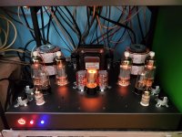
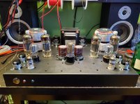
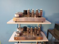
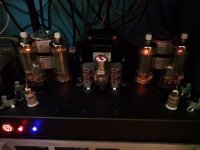
Today I had a chance to work my monoblocs... Nothing I've heard compares to these triode connected >110W RMS Sine @ 30Hz output amps by yours truly IMHO.
Pure bliss in a bad time.
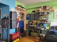
All built in my little "shop" lol
Pure bliss in a bad time.
All built in my little "shop" lol
Attachments
Last edited:
What about 110W with 6P43P triode connected?")
Parallel 10 pairs of them per channel.... But it's cheaper to just use 6P45S or at least 6P36S just from the heater requirements...
Last edited:
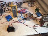
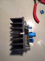
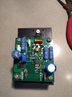
Heres some pics of testing my DHT heater regulator.
This particular unit is 2.5-25V 0.5-5.5A i got boards that can more then double the heater current permissible. Its a voltage controlled CCS with a very long integration time, keeping the internal resistance of the regulator high.
The picture shows the measured ripple at 20V 2A out, my fluke 175 says its about 0.6mV RMS
Attachments
Why do You think AC O-core OT is with good quality, do You measure Sinus signalThanks
from 30-40 to 30000 Hz with scope for distortions? Its not important how cost, but how it sounds from 40-20000 Hz. /600 $ are too much....for 200 $ You can buy big 20 W Ш OTs with good sound from 40 Hz /
I've measured for distortion using sinewave, squarewave, and sawwave on the scope. The 1W power band was usable from 6Hz to ~75kHz. The full power output depends on the tubes and transformers used, but the most powerful one's I've built look clean at 30Hz @ 110W and bandwidth extends beyond 50kHz.. The 10kHz square wave response is very nice, too. For 200$ These effectively make a 100W transformer. Try it for yourself and If you think it's crap you have transformers for your heater supplies.
I also fitted this UCC caps, changed the tubes from 6P36 to 6P45, and changed from VR75 to VR105 because they need more bias voltage. I'm quite pleased with it.
I also fitted this UCC caps, changed the tubes from 6P36 to 6P45, and changed from VR75 to VR105 because they need more bias voltage. I'm quite pleased with it.
Attachments
Today I had a chance to work my monoblocs... Nothing I've heard compares to these triode connected >110W RMS Sine @ 30Hz output amps by yours truly IMHO.
Pure bliss in a bad time.
All built in my little "shop" lol
now Jason, where is that like button? this is an awesome build....

- Home
- Amplifiers
- Tubes / Valves
- Photo Gallery