tube number brotherThe most clean and transparent sound I ever heard...

" Originally Posted by Wavebourn: In Bulgaria they believe in magic, like no FB, no capacitors, no solder, etc..."
Not really. There are many clever people as well. God thanks a BG site which was poisoning the beginner's mind by idiocy almost disappeared. But consequences remain...
Not really. There are many clever people as well. God thanks a BG site which was poisoning the beginner's mind by idiocy almost disappeared. But consequences remain...
Last edited:
In big old computers, connections are made with pins with twisted wires with special revolver,that provide more better degased connection than solders.....
Really good big sound can sense with good sensitivity speakers and with cables not for 2$. Better interstage cap is missing. Is this magic for believing?
Really good big sound can sense with good sensitivity speakers and with cables not for 2$. Better interstage cap is missing. Is this magic for believing?
Last edited:
If I read your question correctly, you are asking if a coupling cap can make a difference. That answer is yes.
Big old computers had different goals than the goals of audio. Only where the goals overlap is the spot for borrowing a method. At the moment, I can't think of a single one.
Big old computers had different goals than the goals of audio. Only where the goals overlap is the spot for borrowing a method. At the moment, I can't think of a single one.
" Originally Posted by Wavebourn: In Bulgaria they believe in magic, like no FB, no capacitors, no solder, etc..."
Not really. There are many clever people as well. God thanks a BG site which was poisoning the beginner's mind by idiocy almost disappeared. But consequences remain...
...and in big old computers with 7 minutes MTBF.
Explanation for young members: the contact pin in old comps has square core. Around it with revolver is twisting wire, that will semi cut 4 times in every turn. If there are 10 turns, wire is cut 40 times. In contact place contact is very clears, almost in vacuum, without deffects.....I made this many times in our manufacturing for big comps....Every time no bad and wrong connections.....
OK, now I get the picture. This type of wire wrapping was used in early receivers like the Pioneer and Sansui and such. Interesting.
I have been looking into the best methods of signal transfer through a physical connection, but I am not getting much in the way of scientific answers. My money says two wires cleaned and bound together before being liquid fluxed and silver soldered then cleaned with alcohol is going to be pretty darn good...just hard to take apart again!
I have been looking into the best methods of signal transfer through a physical connection, but I am not getting much in the way of scientific answers. My money says two wires cleaned and bound together before being liquid fluxed and silver soldered then cleaned with alcohol is going to be pretty darn good...just hard to take apart again!
I have been looking into the best methods of signal transfer through a physical connection, but I am not getting much in the way of scientific answers. My money says two wires cleaned and bound together before being liquid fluxed and silver soldered then cleaned with alcohol is going to be pretty darn good...just hard to take apart again!
Exactly! Wrap a tinned wire around the post, then solder!
If it was good for Soviet, German, US, Canadian, and British military, it is good for me!
Wire wrap is fine if you are in industry where you may make design changes and need to implement them quickly. Where changing the artwork on a 12 layer pc board would drain all of your proffit very quickly. Think telco switches as an example.
In the "old days" where you had wire wrapped computer boards, companies like Telex would do this and pretty much no two were exactly the same.
Its easy to spaz out with specs and use silver solder, ofc wire, blah.....this is just audio here. Your amp wont be pulling 6 G's or be in a high radiation area. Just use regular wire and 60-40 solder and get on with it. Providing that you dont skin the insulation, make cold solder joints, or use crappy components then your amp will likely outlast your interest in it.
Cheese box amplifier
Hi,
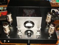
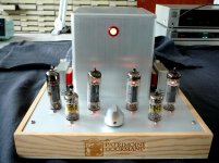
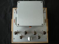
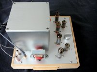
this is a stereo push-pull amplifier built in a cheese box.
The top plate was made by Schaeffer in Germany.
Tubes are 4 x EL84 and 2 x 6AN8.
The main goal of this exercise was the use of 100V transformers as output transformers.
Despite the small 100V output transformers, the amp is powerfull and the sound is not bad at all.
I was inspired by an old posting on the internet:
http://home.alphalink.com.au/~cambie/6AN8amp/6an8amp.htm
Best regards, Frans.
Hi,
this is a stereo push-pull amplifier built in a cheese box.
The top plate was made by Schaeffer in Germany.
Tubes are 4 x EL84 and 2 x 6AN8.
The main goal of this exercise was the use of 100V transformers as output transformers.
Despite the small 100V output transformers, the amp is powerfull and the sound is not bad at all.
I was inspired by an old posting on the internet:
http://home.alphalink.com.au/~cambie/6AN8amp/6an8amp.htm
Best regards, Frans.
Attachments

Hi,
this is a stereo push-pull amplifier built in a cheese box.
The top plate was made by Schaeffer in Germany.
Tubes are 4 x EL84 and 2 x 6AN8.
The main goal of this exercise was the use of 100V transformers as output transformers.
Despite the small 100V output transformers, the amp is powerfull and the sound is not bad at all.
I was inspired by an old posting on the internet:
http://home.alphalink.com.au/~cambie/6AN8amp/6an8amp.htm
Best regards, Frans.
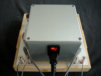
I like the use of the power inlet on the transformer housing instead of below with other wiring. Isolate that from OPTs and that would SEEM to be a good approach.
Cheesus! Nice build!Hi,
this is a stereo push-pull amplifier built in a cheese box.
The top plate was made by Schaeffer in Germany.
Tubes are 4 x EL84 and 2 x 6AN8.
The main goal of this exercise was the use of 100V transformers as output transformers.
I like the use of the power inlet on the transformer housing instead of below with other wiring. Isolate that from OPTs and that would SEEM to be a good approach.
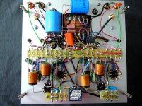
Yes, all power connections and transformer primaries are under the transformer cover, all secondaries are under the chassis plate.
The size of the cheese box determines the dimensions of the chassis top plate,
and the layout leaves no place for the power input and power switch.
The amplifier produces no audible hum or noise, but I doubt that this is the result of the aluminium transformer housing.
Best regards, Frans.
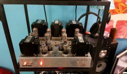
However, PA speakers don't sound as real as Magnepans for which this amp was designed...
https://www.facebook.com/Wavebourn/videos/vb.371503329574641/1369717019753262/?type=2&theater
https://www.facebook.com/Wavebourn/videos/vb.371503329574641/1369717019753262/?type=2&theater
However, PA speakers don't sound as real as Magnepans for which this amp was designed...
https://www.facebook.com/Wavebourn/videos/vb.371503329574641/1369717019753262/?type=2&theater
Probably worth another thread, and maybe you have a build thread somewhere, but what makes it "designed for" Magnepans?
Probably worth another thread, and maybe you have a build thread somewhere, but what makes it "designed for" Magnepans?
Low output impedance, 100W per channel, anti-clipping compressor-limiter that starts on 80W. Also, damper diodes to protect output transformers from blown in Magnepans fuses.
-80 dB of 2'Nd order error on 40W, goes even down with lower power. Higher order errors are below noise level. However, above 40W the tail slowly starts growing. I.e. a 100W per channel push-pull amp that beats SE amps by quality, to beat solid state amps on their territory. If needed, power output can be increased twice by using paralleled GU-50 tubes and 4K output transformers. However, for 200W per channel there will be full power from 40 Hz, to avoid unbearable weight, while the prototype easy delivers 80W per channel from 20 Hz to 20 KHz.
All voltages except +800V and 12.6V for output tubes are stabilized.
It drives well 3-4 way speakers with complex crossovers. During BAF few years ago one of previous prototypes was used to audit nice speakers.
All ideas were discussed on this forum multiple times. I even published here schematic diagram of the driver and phase splitter of this amp (one of previous versions), despite it is a commercial project. I don't hesitate to share my knowledge and experience with people on the forum, but I would not present the complete design for commercial copycats.
- Home
- Amplifiers
- Tubes / Valves
- Photo Gallery