..... assembled with this tape. It took two heavy duty screwdrivers and my full strength!
... I agree, even with some heavy "curses" .... (sorry)
Karel
Thanks!Forgot to say that your amp looked really smart.")
... I agree, even with some heavy "curses" .... (sorry)
Karel

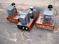
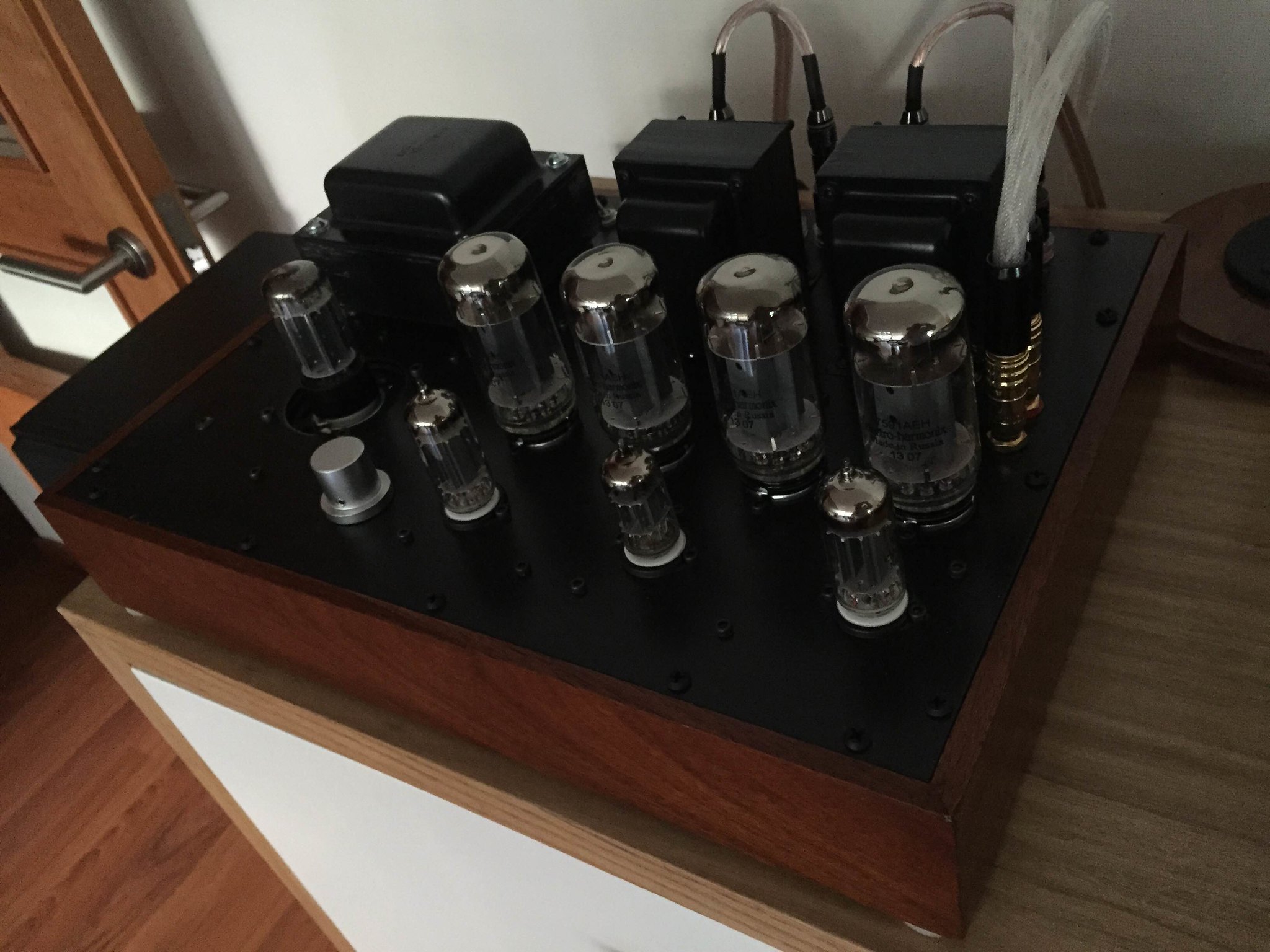
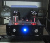
This is my version of a Dyna Stereo 70. The EL34's and transformers are similar, but that's about all. 6SN7 first and second stages, EL34 PP outputs. 0 - 14dB negative feedback only goes back to middle stage diff amp, so better phase margin. Front end is outside of loop. Front end has constant current sink instead of plate R, which drives a follower which has a current source in place of the cathode R. The follower drives the volume control, which then drives the 2nd stage, which is a diff amp, which has a current source in the tail. Switchable Ultra-linear 30W per channel, or Triode-mode 15W per channel. Each EL34 has a bias adjustment pot right next to it, and there's a digital meter that tells you the quiescent current in each tube. The photos are actually obsolete since I got rid of the grid cap front end tube, which picked up a little bit of hum, and replaced it with a 6SN7 - same tube spec wise but no grid cap. Now the hum is reduced to nothing noticeable. The current sink and sources increase linearity, but also power supply hum rejection. I call it, The Musicbox. The keyhole on the front is where you wind it up... (just kidding).
Wow! Impressive build, Bob! Thanks for posting it.
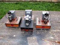
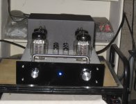
Recently finished this push-pull amplifier. It is basically a Spud in push-pull, hence the Spud-Pull. Two 6E5P per channel, with a phase-inverting input transformer (Reinhofer) and a four-deck stepped attenuator. Both 6E5P share four Cree diodes at the cathode, about 30mA at 200 Volts per 6E5P. Power supply is EZ81 and diodes rectified with pi-filters using R and C. Very simple circuit with a bandwidth of 10 Hz up to 90 Khz (-1dB) with about 3.3 Watts into a 16 ohm load. Only remark is that this amplifier needs full line-out level for max power..
Nice work. I was just reading about the 6E5P as an output tube (as well as the diminutive 417a - what? as an output???). Yeo at diyparadise liked the 417a over the 6E5P and the 6C45Pi as outputs, but I still don't get it...
So how do you like it? Makes me think about somehow using dual triodes as output tubes to make a REAL push pull spud amp... 6AS7 is the obvious choice and I hope to do that, but what about others?
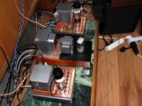
How about this? 6n1p line stage. Small to the eye!
LOVE the rear mounted transformers! Nice work.
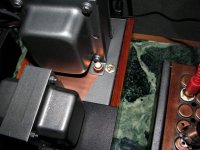
How long does it last in hot conditions? Can't find any data. I still use metal clamps when need to fix something. Probably, it is the result of my education, to design a military equipment...
Yep, my double adhesive for carpets dried pretty fast. Two years and while I did a service all stuff came dropping down - Ouch
 I won't use any again.
...newest diy in my house.... 6BG6GA with 7543 per channel, SE... two rectangular saucer heaters were (again) a flea market find, and they served the purpose like charm... PSU was made with 5BC3 tube... sounds very sweet, and it yet has to break in so... I expect only more smiles, and grins too
Attachments
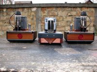
...newest diy in my house.... 6BG6GA with 7543 per channel, SE... two rectangular saucer heaters were (again) a flea market find, and they served the purpose like charm... PSU was made with 5BC3 tube... sounds very sweet, and it yet has to break in so... I expect only more smiles, and grins too
Very nice! Any details you'd like to share regarding the circuit would be appreciated. Interesting looking anode caps.
jeff
Last edited:
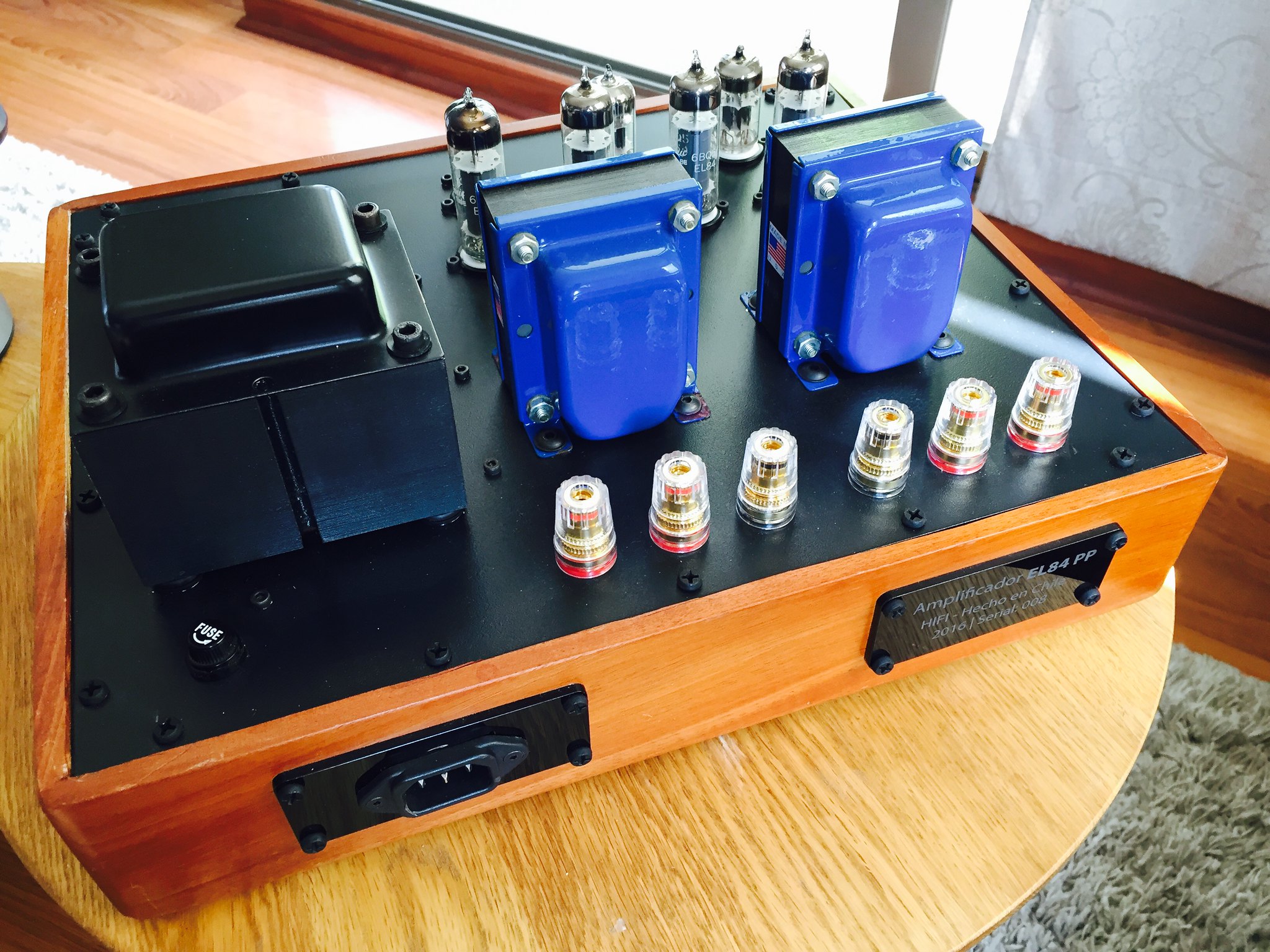
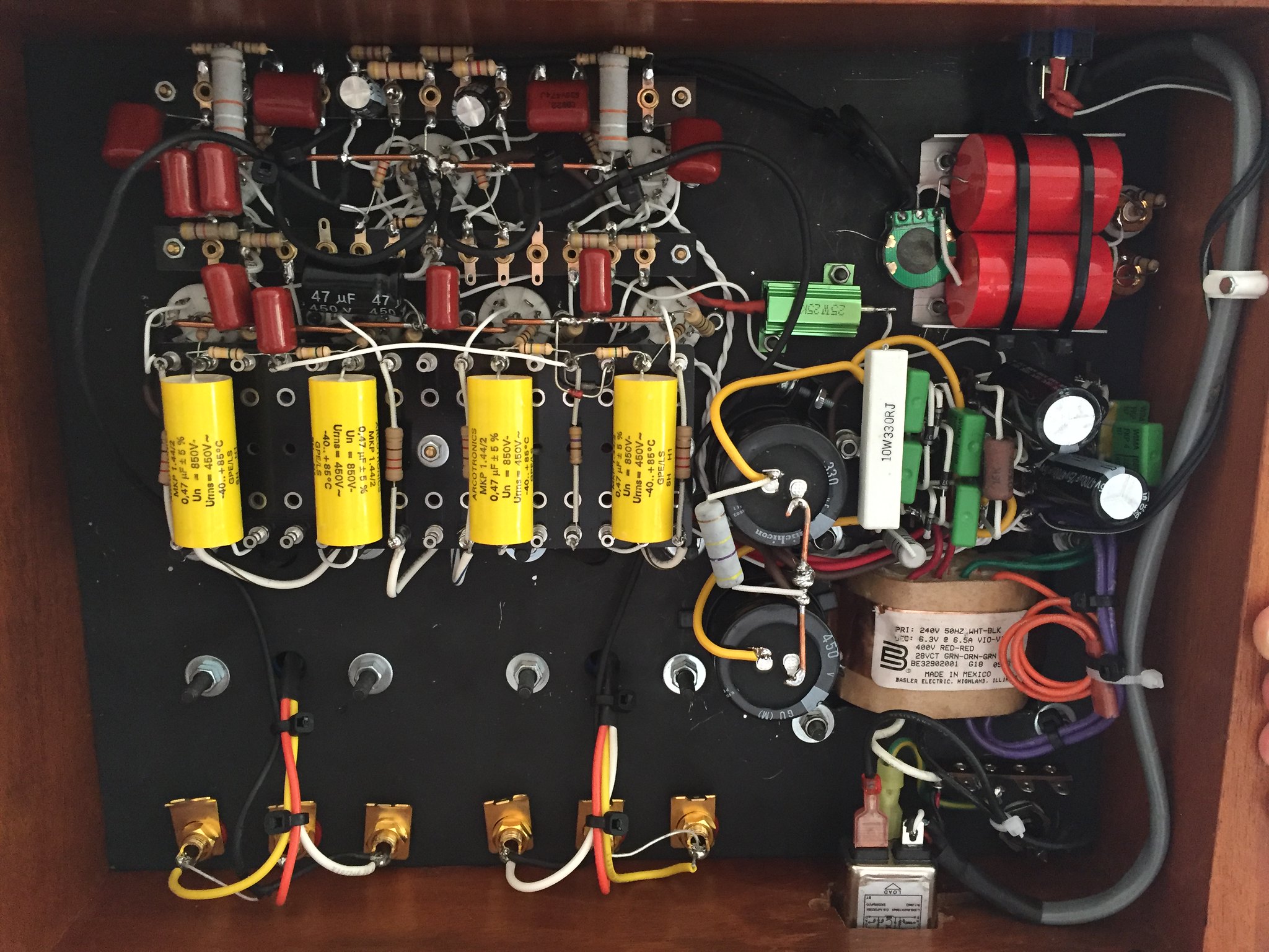
new project, Push Pull El84, 6dJ8 and one 12AX7...
An externally hosted image should be here but it was not working when we last tested it.
Fantástico, gueón, such a wanderfull finish.
na boludo, uruguayo, pero viviendo en chile jajaaja Gracias!!
hectori - very nice, neat, clean, smart build.
Totally agree.
Though I figured you'd say that mhouston, it looks exactly like one of your builds!
Totally agree.
Though I figured you'd say that mhouston, it looks exactly like one of your builds!
Well I was going to add "Classic build". Your right I generally build how you would expect to see a tube amp with minor variations of course.
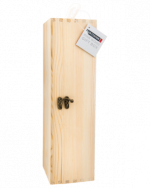
I'm about to build a 6L6 power amp in a wooden bottle box not much bidder than a bottle of wine. Not your classic build.
Attachments
Last edited:
new project, Push Pull El84, 6dJ8 and one 12AX7...
Nice work hector. I seem to recall other projects of yours that were also nice. It looks like this EL84 amp has multiple output taps, but I think of Edcor as only having one output impedance. Were these special order?
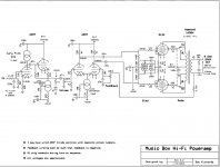
Here's the schematic of my "Musicbox" power amp if anyone's interested. One nice thing about this topology that I don't see very often is the fail-safe bias adjustment circuit for the EL34's. If the wiper of the adjustment pot ever gets dirty and becomes highly resistive or open, the bias applied to the EL34's will go up, instead of down. Down means the EL34 turns on way too much, possibly damaging or blowing the tube. Up means they go into cutoff, which is safe. Nothing damaged. Also notice the passive Rf filter at the input. It minimizes potential slewing related distortions due to any kind of Rf (digital source noise, light dimmer emissions, etc.) that might be riding on the input signal. Also, not everybody realizes that the speaker impedance typically goes way up above 20kHZ, which allows the output transformer to generate rather large voltage transients when the amp is driven into clipping. To keep that under control I've got a Zobel RC across the output terminals, which limits how high the speaker load Z can go at any frequency, as viewed by the output transformer.
Attachments
Last edited:

- Home
- Amplifiers
- Tubes / Valves
- Photo Gallery